

Учебное пособие 2016
.pdfIssue № 3(31), 2016 |
ISSN 2075-0811 |
DESIGNING AND CONSTRUCTION OF ROADS, SUBWAYS,
AIRFIELDS, BRIDGES AND TRANSPORT TUNNELS
UDC 539.3
V. A. Kozlov1
THE DEFLECTED MODE OF MULTI COHERENT PRISMATIC CONSTRUCTIVE
ELEMENTS OF BRIDGE CONSTRUCTIONS
Voronezh State University of Architecture and Civil Engineering Russia, Voronezh, tel.: (473)-276-40-06, e-mail: vakozlov@vgasu.vrn.ru
1D. Sc. in Physics and Mathematics, Head of Dept. of Theoretical and Applied Mechanics
Statement of the problem. The distribution of pressure in building elements of bridge constructions in the period of installation can differ considerably from a field of pressure during operation of a complete object. In some cases bridge flights during this period represent the console with one fixed cross-section. The calculation of the deflected mode of such elements allows one to provide safe installation during the erection of bridges.
Results. The pressure and deformations in a thin-walled multi coherent prismatic construction are defined at the rigid fixed one basic contour and the other one free. As distinct from known works the variable thickness of panels and supporting walls-longerons along a design is considered. The bend from the distributed loading and cross-section force, torsion from the distributed and concentrated moments is considered.
Conclusions. Through the use of the law of variation of a thickness along a construction it is possible to receive redistribution of the pressure arising under the influence of various power factors.
Keywords: deflected mode, building constructions, variable rigidity.
Introduction
Construction of different building structures requires even distribution of strains in construction elements under the effect of applied loads and force to optimize their performance during their operation and assembly. In some cases it is by varying geometric parameters, construction form, change of thickness, ways of fixing, etc. As for bright flights, they are sometimes not a structure supported at both ends during assembly but a console with a fixed longitudinal section where the distribution of strains can differ considerably from that in an assembled flight. Assembly from up to its final stage might take a few years when there will be forces and loads acting on the construction elements as well as low bend and rolling rigidi ty at different stages of assembly. Therefore it is necessary to perform relevant calculations to
© Kozlov V. A., 2016
41

Scientific Herald of the Voronezh State University of Architecture and Civil Engineering. Construction and Architecture
provide safety of the assembly of construction elements in designing bridges and other building structures.
The proposed paper deals with the distribution of strain in a quadruply-connected prismatic structure fixed with a longitudinal set of a regular structure depending on the law of change in the thickness of the upper and lower panels and area of a longitudinal section of longitudinal wall girders. A structure is rigidly fixed along the support contour with a free-end section. The general solutions obtained in the analytical form using the device of special functions for cone and prismatic structures with a random contour of a longitudinal section are in [1, 2], free oscillations are addressed in [3].
Obtaining a resolving system of ordinary differential equations.
The vector of elastic displacement of a random point is presented as a resolution
|
6 n |
|
|
V (z, s) Vi (z) i (s), |
(1) |
||
i 1
where z is longitudinal, s is a transverse coordinates of the point, Vi are unknown generalized displacements determining the displacement of a longitudinal contour z = const, i are corresponding Vi specified coordinate vector functions with i1, i 2 , in are projections of these functions onto unit vectors of a moving trihedron of a medium surface of a prismatic
structure. |
|
|
|
|
|
|
According to [4], the general scheme of resolving differential equations is as follows |
|
|||||
6 n |
a V b V |
b V c V |
|
R / G |
i 1,2,...,6 n, |
(2) |
|
ij j ij j |
ji j ij |
j |
i |
|
|
j 1 |
|
|
|
|
|
|
for the following geometric
Vi |
|
z 0 0 |
i 1,2,...,6 n |
(3) |
|||
|
|||||||
|
|
|
|
|
|||
and static boundary conditions at z l |
|
|
|
|
|
||
|
|
|
|
|
|
||
6 n |
|
|
|
|
|
||
aijVj bijVj |
|
Pi* |
|
i 1,2,...,6 n |
(4) |
||
|
|
||||||
j 1 |
z |
l |
|
z l |
|
||
|
|
||||||
|
|
|
|||||
|
|
|
|
|
|
||
Here unlike [4], a ji , bji , c ji are variable coefficients depending on the character of a range of change in the thickness h z of a structure; Ri , Pi* correspond with surface and concentrated on a free-end section and external loads respectively.
Resolving the system (2) for the original generalized displacements Vi and obeying the obtained solutions to the boundary conditions (3) and (4) using the formulas
42

Issue № 3(31), 2016 |
|
|
|
|
|
|
|
|
|
|
|
|
|
|
|
|
|
|
|
ISSN 2075-0811 |
|
|
|
6 n |
|
|
6 n |
|
|
|
6 n |
|
|
|
|
|
|||||
|
1 Vi i1, |
2 Vi i2 |
, |
12 Vi i2 |
Vi i1 |
. |
|
|||||||||||||
|
|
|
i 1 |
|
|
i 1 |
|
|
|
|
i 1 |
|
|
|
|
|
||||
|
|
|
E |
|
6 n |
|
|
|
, 2 |
|
E |
|
|
6 n |
|
|
|
, |
||
|
|
|
|
|
|
|
|
|
|
|
|
|
|
|||||||
1 |
|
2 |
Vi i1 |
Vi i2 |
|
1 2 |
|
Vi i2 |
Vi i1 |
|||||||||||
|
1 |
i 1 |
|
|
|
|
|
|
|
|
i 1 |
|
|
|
|
|||||
|
|
|
|
|
12 |
|
E |
6 n |
|
|
|
|
|
|
|
|
|
|
||
|
|
|
|
|
|
|
|
|
|
|
|
|
(5) |
|||||||
|
|
|
|
|
|
|
|
|
|
|
|
|
|
|
||||||
|
|
|
|
|
2(1 ) |
Vi i2 |
Vi i1 . |
|
|
|
||||||||||
|
|
|
|
|
|
|
i 1 |
|
|
|
|
|
|
|
|
|
|
|
||
|
|
|
|
|
|
|
|
|
|
|
|
|
|
|
|
|
|
|
|
|
we can find the deformations and strains at a random point of the structure.
There are six generalized displacements Vj determining the displacement of a longitudinal contour z=const as a solid body: three translational V1,V2 ,V3 displacements along the coordinate axes Ох, Оу, Oz and three torsion angles V4 ,V5 ,V6 in relation to these axes for the corresponding functions j1, j 2 , jn , j=1,2,...,6. However in some cases the number of
withdrawn generalized displacements can be reduced. Hence, e.g., for sections symmetrical to the axis Ох, during bending and torsion of a shell from six generalized displacements V1,..., V6 only three can be withdrawn: V2 ,V4 ,V6 . The equilibrium equations corresponding with V1,V3 ,V5
, can be met identically. In order to obtain an analytical solution in the resolution (1) only three
|
|
|
|
|
|
|
|
|
|
|
members will be withdrawn responsible for warping of the sections. The first one V7 (z) 7 (S) |
||||||||||
|
|
|
|
|
|
|
|
|
|
|
account for torsion warping |
and |
|
the |
second |
one |
V8 (z) 8 (S ) for bending |
warping. The |
|||
|
|
|
|
|
|
|
|
|
|
|
components of approximating vector functions i (S ) corresponding to the displacements of a |
||||||||||
longitudinal section as a solid body are as follows |
|
|
|
|
|
|||||
11 21 0, |
31 |
1, |
41 y(S), |
51 x(S ), |
61 0; |
|
||||
|
|
|
|
|
32 |
0, |
42 |
52 |
0, |
|
12 x (S), |
22 y (S), |
|
||||||||
|
|
|
|
|
|
|
|
2n |
|
|
62 x(S) y (S) |
x (S) y(S); |
1n y (S), |
x (S ), |
|
||||||
3n 0, |
4n |
|
|
|
|
|
|
|
(6) |
|
5n 0, 6n x(S)x (S) |
y(S) y (S). |
|||||||||
Warping of longitudinal sections is approximated by two functions:
|
71 |
xy, |
|
2d 1 4d 2 |
x2 y Ky, |
(7) |
|
|
|
81 |
1 |
2 |
|
|
|
where 71 accounts for torsion warping, 81 is bending torsion. Here K is the coefficient of orthogonalization determined using the condition
71(S) 81(S)h(z, S)dS 0.
The components i 2 i3 0 , i = 7,8,...,6+n according to the accepted hypothesis on warping of the contour points in direction to the generating line.
43
Scientific Herald of the Voronezh State University of Architecture and Civil Engineering. Construction and Architecture
Besides if a longitudinal section has two symmetry axes: in relation to Ox and Oy , a number of the coefficient of the system (2) become zero. In this case the connected system of five differential equations is split into two: the first, second and fifth equations describe the bending of a structure and the third and fourth one torsion. These systems are as follows for a symmetrical contour of a longitudinal section
a V |
|
|
|
|
|
|
|
b V |
|
b V |
|
|
|
|
|
R / G, |
|||||||
|
a V |
|
|
|
b V |
b V |
|||||||||||||||||
|
22 |
|
2 |
|
22 |
|
2 |
24 |
|
4 |
28 |
8 |
24 |
4 |
28 |
8 |
|
2 |
|||||
|
|
|
|
|
|
|
|
|
|
|
|
|
|
|
c44V4 |
c48V8 |
R4 / G, |
(8) |
|||||
a44V4 |
a44V4 |
b24V2 |
|||||||||||||||||||||
|
|
|
|
|
|
|
|
|
|
|
|
|
|
|
|
|
|
|
|
|
|
|
|
|
|
|
|
|
|
|
|
|
|
|
|
|
|
c48V4 c88V8 R8 / G. |
|
||||||||
a88V8 |
a88V8 |
b28V2 |
|
||||||||||||||||||||
a V |
|
a |
|
V |
|
b V |
|
|
|
|
R / G, |
|
|
|
|||||||||
|
|
|
|
|
|
|
b V |
|
|
|
|
||||||||||||
|
66 |
6 |
66 |
6 |
67 |
7 |
67 |
7 |
|
6 |
|
|
|
|
|||||||||
|
|
|
|
|
|
|
|
|
|
|
|
|
|
|
|
|
|
|
|
|
|
|
(9) |
a V |
a |
V |
|
b V |
|
c V R / G. |
|
|
|
||||||||||||||
|
77 |
7 |
|
77 |
7 |
67 |
6 |
77 |
7 |
|
7 |
|
|
|
|
||||||||
For a rigidly fixed structure loaded at the end section z=l by a concentrated longitudinal force
Qy and Мz, geometric (3) and statical (4) boundary conditions respectively are as follows:
V2 |
|
z 0 0, |
V4 |
|
z 0 0, |
V8 |
|
z 0 0; |
|
|
|
|
|
|
|
|
(10) |
||||||||
|
|
|
|
|
|
|
|
|
|
|
|||||||||||||||
|
|
|
|
|
|
|
|
|
|
|
|||||||||||||||
a22V2 b24V4 b28V8 |
|
|
|
|
|
|
|
V4 |
|
|
V8 |
|
|
||||||||||||
|
z l Qy / G, |
|
z l 0, |
|
z l 0. |
||||||||||||||||||||
|
|
|
|||||||||||||||||||||||
V6 |
|
z 0 0, |
V7 |
|
z 0 0, |
V7 |
|
z l 0; |
a66V6 b67V7 |
|
z l |
M z / G. (11) |
|||||||||||||
|
|
|
|
||||||||||||||||||||||
|
|
|
|
||||||||||||||||||||||
Furthermore the solution of groups of differential equations (8) and (9) for corresponding boundary conditions (10) and (11) is performed individually.
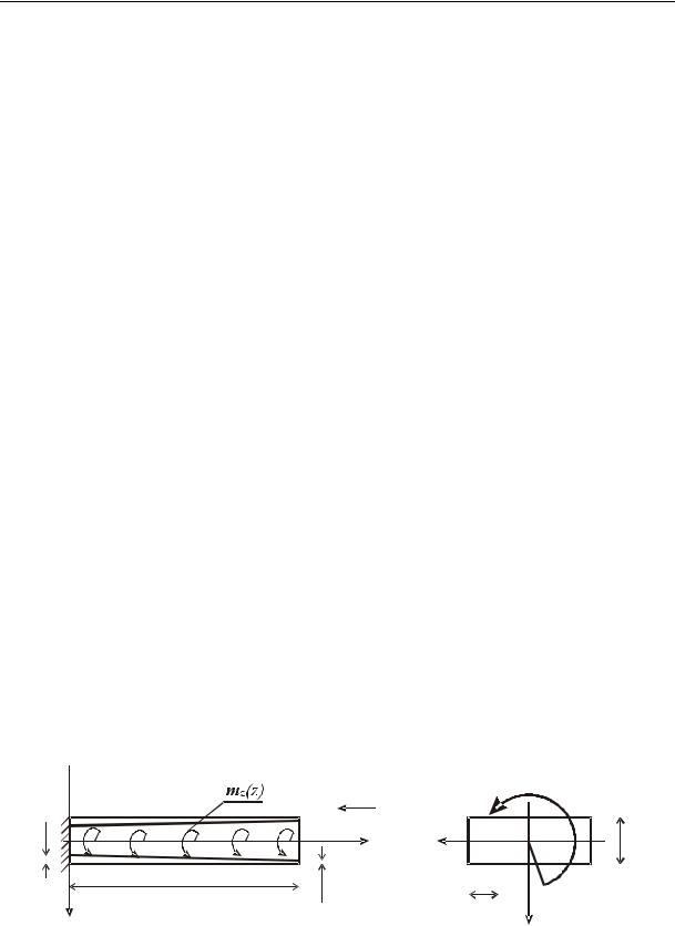
Bending torsion. Let us solve the problem of torsion of the structure using the distributed mz(z) and concentrated Mz in the section z=l moments (Fig.1).
|
|
|
|
|
|
|
|
|
|
|
View А |
||||
|
|
|
|
|
|
|
|
A |
|
|
Вид А |
||||
|
|
|
|
|
|
|
|
|
|
|
M |
||||
|
|
|
|
|
|
|
|
|
|
|
|
|
z |
||
h1 |
O |
|
|
|
|
z |
x |
|
|
|
|
|
|
||
|
|
|
|
|
|
|
|
|
|
d |
|||||
|
|
|
|
|
|
|
|
|
|
|
|
||||
|
|
|
|
|
|
|
|
|
|
|
|
|
1 |
||
|
|
|
|
l |
|
|
|
|
|
|
|
|
|
|
|
|
|
|
|
|
|
|
|
|
|
|
|
|
|
|
|
|
|
|
|
|
h |
|
d2 |
|
|
|
|
|
|||
|
|
|
|
|
|
|
|
||||||||
|
|
|
y |
|
2 |
|
|
|
|
y |
|||||
|
|
|
|
|
|
|
|
|
|
|
|||||
|
|
|
|
|
|
|
|
|
|
|
|
||||
|
|
|
|
|
Fig. 1 |
|
|
|
|
|
|
|
|||
44
Issue № 3(31), 2016 |
ISSN 2075-0811 |
In this case in the system (9) R6=mz(z), R7=0. Let the thickness of the structure h(z) and distributed torque moment mz(z) change linearly along the generating line going down from h1 to h2 and from m1 to m2 respectively as the free end approaches
|
|
h h(z) b z, |
mz (z) z m1, |
where b h1 , |
(h1 |
h2 ) / l , (m2 m1) / l; |
l is the length of the structure. |
Following the transformations of the system (9) we end up with a heterogeneous Bessel differential equation in relation to the generalized torsion warping
V7 1V7 aV7 1A1 A2 A3 , |
(12) |
where b / z; a, A1, A2 , A3 are the coefficients depending on the geometric parameters of the structure.
The general integral of a heterogeneous differential equation (12) is written using the mod-
ified first-order I0 and the second-order Bessel equations K0 |
as in [5] as well as the Struve |
|||||||||||||
function L0 . Ultimately the expressions for generalized displacements are as follows |
|
|||||||||||||
|
|
|
|
|
|
|
Fz2 Rz C dz C |
|
|
|
|
|||
V |
b67 |
|
V dz |
|
|
|
, |
|
||||||
|
2 |
|
||||||||||||
6 |
|
|
|
|
7 |
1 |
|
|
|
(13) |
||||
|
|
a |
66 |
|
|
|
|
|
|
|
||||
|
|
|
|
|
||||||||||
V7 C3I0 C4 K0 ( A1 A3 / a)L0 / 2 |
|
a ( A2 A3 ) / a. |
|
|||||||||||
Integration constants are identified using the boundary conditions (11) of the task. Knowing the expressions for the generalized displacements it is not difficult to identify the deformations and strains at a random point of the structure using the formulas (5).
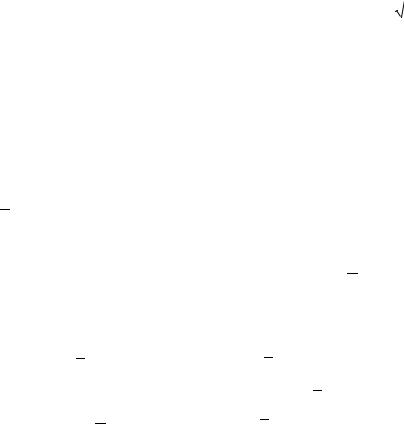
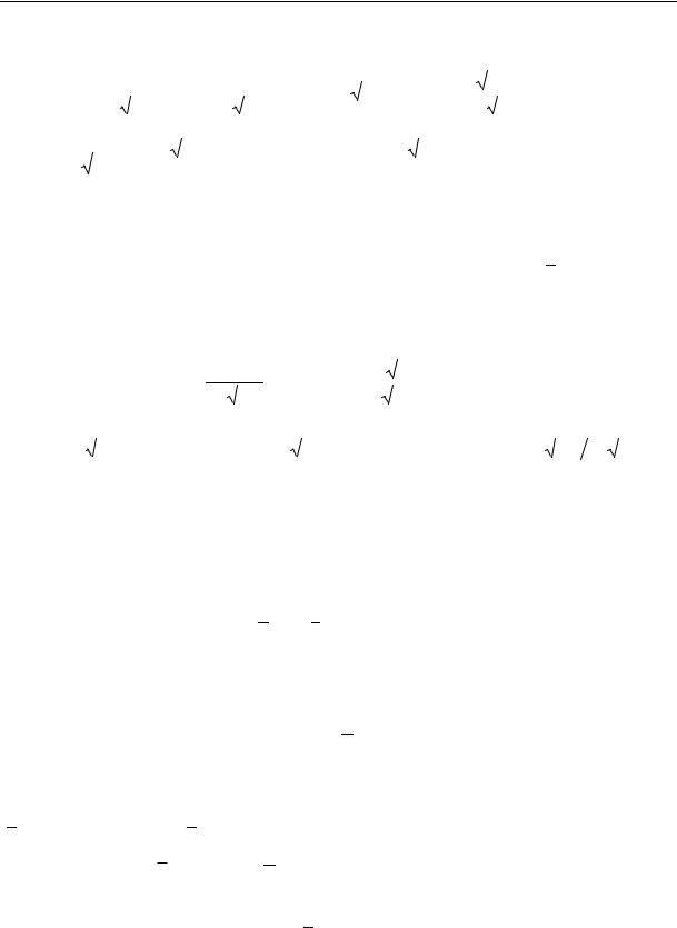
According to the obtained solutions for a prismatic structure of a linear variable thickness the number of calculations using software was performed. As an example in Fig. 2 there is a model
of |
the structure, its loading scheme and graphs of |
the dependence of normal strains |
||||
1 |
1 / E f ( |
|
) depending on |
|
z / l . In the calculations Mz= 1.47 kN m, mz = 1.47 kN m, |
|
z |
z |
|||||
d1 = 8 10-2 m, d2 = 1.6 10-1 m, |
l = 1 m, h1 = 10-3 m, |
h2 = 0.9 10-3 and h2 = 0.2 10-3 m. |
||||
The curved lines 1 and 2 describe the distribution 1 |
along the longitudinal rib (x=-2d2, |
|||||
у=-d1/2) of the upper panel of the structure loaded with a moment mz and the curved lines 3 and 4 for a combination of the torsion with the moments Mz and mz. The graphs 1 and 3 are designed at h h1 / h2 = 1.1 and 2and4at h 5.
A comparative analysis shows that even at h = 1.1 a concentrated moment Mz considerably increases 1 (curved line 3) and at h 5 there is a qualitative change of the strain of the
45
Scientific Herald of the Voronezh State University of Architecture and Civil Engineering. Construction and Architecture
structure (curved line 4). For the latter at z = 0.8 there is a surge of strains caused by change in the area of a normal section. The above graphs indicate that in multi-connected shell structures of a constant and variable rigidity warping strains 1 do not have the edge effect as in rods with a solid section and going down depending on the embedding plane are distributed along the entire shell. In the end section due to its free warping these strains equal zero.
Curved
line
Using the rib: x = –2d2, y = –d1/2
1; 2 – Torsion mz,
3; 4 – Torsion mz
and Mz
Fig. 2
46
Issue № 3(31), 2016 |
ISSN 2075-0811 |
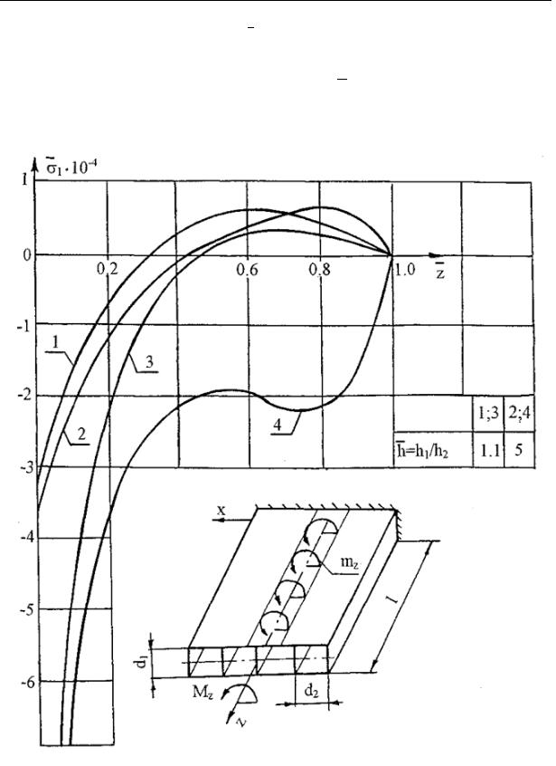
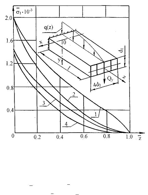
Warping bend. Let us look at a warping bend of a quadruply-connected prismatic structure with a symmetrical square contour. From the external loads we accept the distributed load q ( z ) and a concentrated force Qy at the free end as shown in Fig. 3.
|
|
|
|
q(z) |
|
|
|
|
|
|
View A |
||||
|
|
|
|
|
|
|
|
|
|
|
Вид А |
||||
|
|
|
|
|
|
|
|
A |
|
|
|
|
|
|
|
h1 |
|
|
|
|
z |
x |
|
|
|
|
|
|
|||
|
|
|
O |
|
|
|
|
|
|
|
|
d1 |
|||
|
|
|
|
|
|
|
|
|
|
||||||
|
|
|
|
|
|
|
|
|
|
|
|
|
|||
|
|
|
|
|
|
|
|
|
|
|
|
|
|
||
|
|
|
|
|
|
|
|
|
|
|
|
|
|
|
|
|
|
|
|
|
|
|
|
|
|
|
|
|
|
|
|
|
|
|
|
|
|
|
|
|
|
|
|
|
|
|
|
|
|
|
|
|
|
|
|
|
|
d2 |
_ |
|
|
|
|
|
|
|
|
_ |
|
h2 |
|
|
Q y |
||||||
|
|
|
|
|
|
|
|
||||||||
|
|
|
y |
Q y |
|
|
|
|
|
|
|
y |
|||
|
|
|
|
|
|
|
|
|
|
|
|
||||
Fig. 3
Taking into account the character of loading in the equation system (8) describing the bend of the structure we get R2 (z) q(z), R4 0, R8 0 . For the sake of certainty we assume that the distributed load q(z) obeys the parabolic law for the linear law of change of thickness h(z)
q(z) q z2 |
q z q , |
q (q q l) / l2 |
, |
|||
1 |
2 |
3 |
1 |
3 |
2 |
|
where q2 and q3 determine the longitudinal load in the section z = 0 and the character of changes of the parabola along the axis z respectively.
As for the torsion, the general integral of a heterogeneous Bessel differential equation in relation to the generalized bending warping is written as a sum of the solutions of a homogeneous equation using the modified first-order 0 and second-order 0 Bessel function and particu-
lar solutions identified using the method of variation of the Lagrangian constants. Ultimately the isolated form of the obtained solutions is the following:
|
|
C1B0 RB1 FB2 HB3 |
|
|
|
|
|
|
|
|
|
|
|
|
|
|
|
||||||||||
|
V |
|
|
V dz |
b28 |
|
|
V dz, |
|
|
|
||||||||||||||||
|
|
|
|
|
|
|
|||||||||||||||||||||
|
2 |
|
|
|
a |
|
|
|
|
4 |
|
a |
|
|
8 |
|
|
|
|||||||||
|
|
|
|
|
|
|
|
|
|
|
|
|
|
|
|
|
|
|
|
|
|
|
|
|
|
||
|
|
|
|
|
|
22 |
|
|
|
|
|
|
22 |
|
|
|
|
|
|
|
|
||||||
|
V4 C4 B0 C1B1 RB2 / 2 FB3 / 3 HB4 / 4 / |
|
44 C5 , |
|
|||||||||||||||||||||||
|
a |
|
|||||||||||||||||||||||||
|
V8 C2 0 |
C3 0 |
~ |
|
~ |
~ |
|
|
|
~ |
~ |
|
|
|
~ |
|
|
|
|
~ |
|
||||||
|
(A1 |
A3 |
/ a)L0 / 2 |
|
a |
[A2 A3(r z)]/ a |
|||||||||||||||||||||
|
|
~ |
|
|
|
|
|
3 |
|
|
|
|
|
3 |
|
|
|
|
|
|
|
|
|
||||
|
|
A4[ 0 0 (r z) dz |
0 0 (r z) |
dz], |
|
|
|
||||||||||||||||||||
where |
|
|
|
|
|
|
|
|
|
|
|
|
|
|
|
|
|
|
|
|
|
|
|
|
|
|
|
B (z) rB |
(z) |
zi |
(i 1,2,3,4), |
B |
|
|
ln(b z) |
, |
|
|
r |
b |
, |
|
|||||||||||||
|
|
|
|
|
|
|
|
|
|
|
|
|
|||||||||||||||
i |
i 1 |
|
|
i |
|
|
|
|
|
0 |
|
|
|
|
|
|
|
|
|
|
|
|
|
||||
|
|
|
|
|
|
|
|
|
|
|
|
|
|
|
|
|
|
|
|
|
|
||||||
47
Scientific Herald of the Voronezh State University of Architecture and Civil Engineering. Construction and Architecture
С3
|
|
|
|
|
|
C1 Qy / G l R l F Hl , |
|
C2 D1 C3D2 , |
|
|
|
|
|
|
|
|
|||||||||||||||||||
|
|
|
|
|
|
|
|
|
|
|
|
|
|
|
|
|
|
|
|
|
|
L 1 |
~ |
|
l) |
|
|
|
~ |
|
|
|
|||
|
|
|
|
|
|
|
1 |
|
|
|
|
|
|
~ |
|
|
|
|
|
|
~ |
|
|
A3 |
|
||||||||||
|
|
|
|
|
|
|
|
|
|
|
|
|
|
|
|
|
|
a (r |
|
|
|
||||||||||||||
|
D2 1 |
~ |
|
|
~ |
|
|
|
D1 1 |
a (r l) |
|
|
|
~ |
A1 |
|
|
~ |
|
|
|
||||||||||||||
|
a (r l) 1 |
a (r l) |
|
|
|
|
|
|
|
|
|
|
2 a |
|
|
|
|
a |
|
|
|||||||||||||||
|
~ |
|
|
~ |
|
~ |
|
|
|
3 |
|
|
|
|
|
|
|
~ |
|
|
|
|
|
3 |
|
|
|
|
|
|
|||||
|
|
|
|
|
|
|
|
|
|
|
|
|
|
|
|
|
|
|
|
|
|
|
|
||||||||||||
|
A3 |
|
|
|
|
|
|
|
|
|
|
|
|
|
|
|
|
|
|
|
|
|
, |
|
|
||||||||||
|
|
|
|
A |
a (r l) |
0 |
(r z) |
dz |
|
|
|
|
a (r |
l) |
|
0 |
(r z) |
dz |
|
|
|
|
|||||||||||||
|
~3 |
|
|
4 |
1 |
|
|
|
|
|
|
|
|
z l |
1 |
|
|
|
|
|
|
|
|
|
z l |
|
|
|
|||||||
|
|
|
|
|
|
|
|
|
|
|
|
|
|
|
|
|
|
|
|
|
|
|
|
|
|
|
|
|
|||||||
|
|
a |
|
|
|
|
|
|
|
|
|
|
|
|
|
|
|
|
|
|
|
|
|
|
|
|
|
|
|
|
|
|
|
||
|
|
|
|
|
|
|
|
|
|
|
R |
|
F |
|
|
Hl |
|
|
|
|
|
|
|
|
|
|
|
|
|||||||
|
|
|
|
|
|
|
C4 |
l C1 |
l |
|
|
l |
|
|
|
|
|
, |
|
|
|
|
|
|
|
|
|
|
|
||||||
|
|
|
|
|
|
|
|
|
|
|
|
|
|
|
|
|
|
|
|
|
|
|
|
||||||||||||
|
|
|
|
|
|
|
|
|
|
|
|
2 |
|
3 |
|
|
4 |
|
|
|
|
|
|
|
|
|
|
|
|
|
|
||||
С5 С4 B0 (0) C1B1(0) RB2 (0) / 2 FB3 (0) / 3 HB4 (0) / 4 / a44,
|
|
|
|
C1B0 (0) RB1(0) FB2 (0) HB3 (0) |
|
|
|
|
|
|
|
|
|
|
|
|
|
|
|
|
|
|
|
|
|
||||||||||||||||||||||||||
|
|
|
C |
|
|
V dz |
|
|
|
|
b28 |
|
V dz |
|
|
, |
|
|
|
||||||||||||||||||||||||||||||||
|
|
|
|
|
|
|
|
|
|
|
|||||||||||||||||||||||||||||||||||||||||
|
|
|
|
|
|
|
|
|
|
|
|
|
|
|
|
||||||||||||||||||||||||||||||||||||
|
|
|
|
6 |
|
|
|
|
|
|
|
|
|
|
|
|
|
|
|
|
|
|
|
|
|
|
|
|
4 |
|
|
z 0 |
|
|
22 |
|
|
8 |
|
|
z 0 |
|
|
|
|
||||||
|
|
|
|
|
|
|
|
|
|
|
|
|
|
a |
22 |
|
|
|
|
|
|
|
|
|
L |
|
|
|
|
|
|
|
|
a |
|
|
|
|
|
|
|
|
|
||||||||
|
|
|
|
|
|
|
|
|
|
|
|
|
|
|
|
|
~ |
|
~ |
|
|
|
|
~ |
|
|
|
|
|
|
|
~ |
|
|
|
|
|
|
|
|
|
|
|
|
|
|
|
|
|||
|
|
|
|
|
|
|
|
|
|
|
|
1 |
|
|
A |
|
rA |
|
|
|
|
|
|
|
|
|
|
A |
|
|
|
|
|
|
|
|
|
|
|
|
|
|
|
||||||||
|
|
|
|
|
|
|
|
|
D1 |
|
|
|
|
|
|
|
|
a r |
|
|
|
|
|
|
|
|
|
|
|
|
|
|
|||||||||||||||||||
|
|
|
|
|
|
|
|
|
|
|
~ |
|
|
|
~ |
~ |
|
|
|
0 |
~ |
|
|
A1 |
|
~ |
|
|
|
|
|
|
|
|
|
|
|
||||||||||||||
|
|
|
|
|
|
|
|
|
|
0 |
a r |
|
|
|
2 |
|
3 |
|
|
|
|
|
|
|
|
~ |
|
|
|
3 |
|
|
|
|
|
|
|
|
|
|
|
|
|
|
|
|
|||||
|
|
|
|
|
|
|
|
|
|
|
a |
|
a |
|
|
|
|
2 a |
|
|
|
|
|
|
|
|
a |
|
|
|
|
|
|
|
|
|
|
|
|
|
|
|
|||||||||
~ |
|
|
|
~ |
|
|
|
3 |
|
|
|
|
|
|
~ |
|
|
|
|
|
3 |
|
|
|
|
|
|
|
|
D |
|
|
~ |
|
|
|
~ |
||||||||||||||
|
|
|
|
|
|
|
|
|
|
|
|
|
|
|
|
|
|
|
|||||||||||||||||||||||||||||||||
|
|
|
dz |
|
|
|
|
|
|
|
dz |
|
, |
|
|
||||||||||||||||||||||||||||||||||||
A |
0 |
a r |
0 |
(r z) |
|
|
0 |
a r |
0 |
(r z) |
|
0 |
a r |
0 |
a r . |
||||||||||||||||||||||||||||||||||||
4 |
|
|
|
|
|
|
|
|
z 0 |
|
|
|
|
|
|
|
|
|
|
|
|
|
|
|
z 0 |
|
|
|
2 |
|
|
|
|
|
|
|
|
|
|
|
|
||||||||||
|
|
|
|
|
|
|
|
|
|
|
|
|
|
|
|
|
|
|
|
|
|
|
|
|
|
|
|
|
|
|
|
|
|
|
|
|
|
|
|
|
|
|
|
|
|
|
|
||||
|
|
|
|
|
|
|
|
|
|
|
|
|
|
|
|
|
|
|
|
|
|
|
|
|
|
|
|
|
|
|
|
|
|
|
|
|
|
|
|
|
|
|
|
|
|
|
|||||
|
|
|
|
|
|
|
|
|
|
|
|
|
|
|
|
|
|
|
|
|
|
|
|
|
|
|
|
|
|
|
|
|
|
|
|
|
|
|
|
|
|
|
|
|
|
|
|
|
|
|
|
Having determined the displacements according to the formulas (5) deformations and strains are found at a random point.
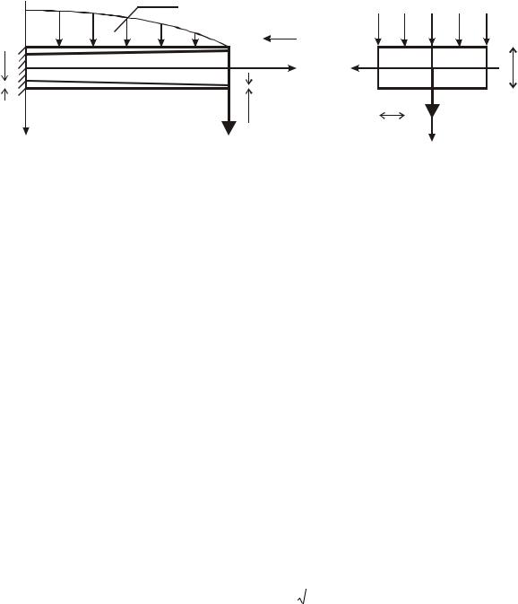
Fig.4 presents some of the results of numerical calculations of a quadruply-connected model structure with the thickness of panels and longitudinal walls changing according to the linear law. The dependence graphs 1 f (z) at the joint effect of the force Qy on the model
distributed along the loading range |
q(z) q2 z q3 |
, |
where |
q2 = -15/l, q3 = 19.6 kN/m. For |
|||||
|
|
|
|
|
|
||||
the calculations l = 1 m, h1 = 10-3 |
m, d1 = 8 10-2 |
m, d2 = 1,6 10-1 m, |
|
= 1.1 and 5. The |
|||||
h |
|||||||||
curved lines 3 and 4 describe the distribution 1 f ( |
|
) |
along the side rib of the upper pan- |
||||||
z |
|||||||||
el given by the coordinates x = 2d2, y= -d1/2 on the linear load q(z) and the curved lines 1 and 2 at the joint operation of Qy = 1.96 kN and q(z). The graphs 2 and 4 are designed at h = 1.1 and 1 and 3 at h = 5. The nature of the curved lines un this case is identical and they are different in 1. A drop in 1 to the end section is in full agreement with the operation of the structure.
Note that in the specific transition at h 1 the calculation results are consistent with those known from literature [6], which proves the credibility of the results and numerical calculations.
48
Issue № 3(31), 2016 |
ISSN 2075-0811 |
Fig. 4
Conclusions
The analysis of the above graphs shows that for the linear law of change of the thickness the nature of distribution 1 in the range for h =1.1 is the same as for the structure of the constant thickness [6]. However as h increases, 1 differs in the module from the strains at h const .
Hence for the above loading schemes the strain-deformation of prismatic thin-walled structures with constant and variable thickness is different, which should be considered in calculations of the elements of actual building structures. Hence by varying the law of change of the thickness of the structure and thus its rigidity redistributions of strains caused by different forces can be identified.
49

Scientific Herald of the Voronezh State University of Architecture and Civil Engineering. Construction and Architecture
References
1.Bulatov S. N., Kozlov V. A. Reshenie nekotorykh prikladnykh zadach teorii koniche-skikh obolochek slozhnoy geometrii [The solution of some applied problems of the theory of conical shells of complex geometry]. RAN. Problemy mashinostroeniya i nadezhnosti mashin, 2000, no. 5, pp. 102––108.
2.Bulatov S. N., Kozlov V. A. Stesnennyy izgib s krucheniem konsol'no zashchemlennoy tsilindricheskoy obolochki s mnogosvyaznym konturom nekrugovogo ochertaniya [Constrained bending and torsion of a cantilever clamped cylindrical shell with mesh contour noncircular shape]. Vestnik Voronezhskogo GASU. Dorozhno-transportnoe stroitel'stvo, 2004, no. 2, pp. 21––23.
3.Kozlov V. A. Free vibrations of console restrained and prismatic thin-slab structures. Scientific Herald of the Voronezh State University of Architecture and Civil Engineering. Construction and Architecture, 2014, no. 3 (23), pp. 7–19.
4.Obraztsov I. F., Onanov G. G. Stroitel'naya mekhanika skoshennykh tonkostennykh system [Structural mechanics sloping thin-walled systems]. Moscow, Mashinostroenie Publ., 1973, 659 p.
5.Kamke E. Spravochnik po obyknovennym differentsial'nym uravneniyam [Handbook on ordinary differential equations]. Nauka Publ., 1976, pp. 142––144, 398––403.
6.Obraztsov I. F. Variatsionnye metody rascheta tonkostennykh aviatsionnykh prostranstvennykh konstruktsiy
[Variational methods of calculation of thin walled aircraft constructions]. Mashinostroenie Publ., 1966. 392 p.
7.Seredin P.V. Spinodal'nyy raspad v epitaksial'nykh tverdykh rastvorakh geterostruktur ALXG1XAS/GAAS(100) i GAXIN1-XP/GAAS(100). Izvestiya Samarskogo nauchnogo tsentra Rossiyskoy akademii nauk, 2009, vol. 11, no. 3––1, pp. 46––52.
50