
Будова перевірка та дослідження South NTS 352R(L) / MANUAL ET SOUTH NTS350R ING
.pdf
Enter Scale Factor in the same way |
|
|
|
|
|
|
|
F1 |
|
|
GRID FACTOR |
|
|
|
|
|
|
|
||
Grid Factor is display for 1 to 2 second |
|
|
|
|
= 1.000685 |
|
Enter ELEV |
|
|
||||
|
|
|
|
|||
and display returns to Layout menu 2/2. |
|
|
|
|
|
|
|
F4 |
|
|
|
|
|
|
|
|
|
|
|
|
|
|
|
|
|
|
|
|
|
|
|
|
|
|
*1 Refer to Section 5.8 “How to Enter Alphanumeric characters”
Input Range Elevation -9999 to +9999m -32805 to +32805ft.ft+in
Scale factor 0.990000 to 1.010000
13.2.2 Selecting Coordinate Data File
You can execute a Layout from selected coordinate data file, also you can record New point measured data into the selected coordinate data file.
The only coordinate data file existing can be selected and you can not make a new file in this mode for more information about file, refer to Chapter 11 “MEMORY MANAGEMENT MODE”.
When LAYOUT MODE is begun, a file can be selected in the same way.
Operation procedure |
Operation |
|
|
Display |
|
|
||
|
|
|
|
|
|
|
|
|
|
|
|
LAYOUT |
|
|
|
2 / 2 |
|
|
|
|
F1 SELECT |
A |
FILE |
|
||
|
|
|
F2 NEW |
POINT |
|
|
||
Press the F1 (SELECT A FILE) key from |
|
|
F3 GRID |
FACTOR P↓ |
|
|||
F1 |
|
|
|
|
|
|
|
|
|
|
|
|
|
|
|
||
the layout menu 2/2. |
|
|
|
|
|
|
|
|
|
|
|
|
|
|
|
|
|
|
|
|
SELECT |
A |
FILE |
|
|
|
|
|
|
FN ___________ |
|
|
|||
|
|
|
INPUT |
LIST |
--- |
ENTER |
|
|
|
|
|
|
|
|
|||
|
|
|
|
|
|
|
|
|
|
|
|
COORDDATA |
/C0352 |
|
|||
Press the F2 (LIST) key to display the |
F2 |
|
->*DATA |
/C0228 |
|
|
||
list of coordinate data file. *1 |
|
SATADDATA |
/C0080 |
|
||||
|
|
|
||||||
|
|
|
--- SRCH |
--- |
ENTER |
|
||
|
|
|
|
|
|
|
|
|
97
PDF "pdfFactory Pro" www.fineprint.com.cn

|
|
|
|
|
|
|
|
Scroll file list by pressing the [▲] or [▼] |
|
|
*DATA /C0228 |
|
|
||
[▲]or[▼] |
|
SATADDATA |
/C0080 |
|
|||
key and select a file to use *2 3 |
|
|
|
|
|
|
|
|
|
KLLLSDATA |
/C0085 |
|
|||
|
|
|
--- SRCH |
|
--- |
ENTER |
|
|
|
|
|
|
|
|
|
|
|
|
|
|
|
|
|
|
|
|
LAYOUT |
|
|
2 / 2 |
|
Press the F4 (ENTER) key |
F4 |
|
F1 SELECT |
A FILE |
|
||
The file will be set |
|
F2 NEW |
POINT |
|
|
||
|
|
|
|
||||
|
|
|
F3 GRID |
FACTOR |
P↓ |
|
|
|
|
|
|
|
|
|
|
*1 If you want to input file name directly, press the [F1](INPUT)key and enter a file name. *2 When a file has been selected already, a mark is indicated on left of current file name. *3 For the file discrimination mark (* @ &), refer to Section 14.3 “FILE MAINTENANCE”
13.2.3 Setting Occupied Point
Occupied point can be set by two setting methods as follow:
1)Setting from the coordinate data stored in the internal memory
2)Direct key input of coordinate data
Setting the occupied point from the internal coordinate data file.
Operation procedure |
|
Operation |
|
|
Display |
|
|
|
Press the F1 OCC.PT INPUT key |
|
|
|
|
|
|
|
|
|
|
OCC.PT |
|
|
|
|||
from the Layout menu 1/2. |
|
F1 |
|
PT# ___________ |
|
|
||
|
|
|
|
|
|
|
||
The previous data is shown. |
|
|
|
INPUT |
LIST |
NEZ |
ENTER |
|
|
|
|
|
|
||||
|
|
|
|
|
|
|
|
|
|
|
|
|
|
|
|
|
|
|
|
|
|
OCC.PT |
|
|
|
|
Press the F1 (INPUT) key |
|
F1 |
|
PT# = PT-01 |
|
|
|
|
|
|
|
|
|
|
|
||
|
|
|
|
BACK |
SPAC |
NUM |
[ENT] |
|
|
|
|
|
|
|
|
||
|
|
|
|
|
|
|
|
|
|
|
|
|
INSTRUMENT |
HEIGHT |
|
||
Enter PT#, press the F4 (ENT) key |
*1 |
Enter PT# |
|
INPUT |
|
|
|
|
F4 |
|
INS. HT: |
0.000 m |
|
||||
|
|
|
|
|||||
|
|
|
|
INPUT |
--- |
--- |
ENTER |
|
|
|
|
|
|
|
|
|
|
98
PDF "pdfFactory Pro" www.fineprint.com.cn
|
|
|
|
|
|
|
|
|
|
|
F1 |
|
LAYOUT |
|
|
1 / 2 |
|
Enter INS HT in the same way |
|
|
F1 OCC.PT |
INPUT |
|
|||
|
Enter INS.HT |
|
|
|||||
The display returns to layout menu 1/2. |
|
|
F2 BACKSIGHT |
|
|
|||
|
F4 |
|
|
|
||||
|
|
|
F3 LAYOUT |
|
P↓ |
|
||
|
|
|
|
|
|
|||
|
|
|
|
|
|
|
|
|
*1 Refer to Section 5.8 “How to Enter Alphanumeric characters”. |
|
|
|
|
||||
Example setting: Setting instrument point coordinates directly |
|
|
|
|
||||
Operation procedure |
|
Operation |
|
|
Display |
|
|
|
|
|
|
|
|
|
|
|
|
Press the F1 OCC.PT INPUT key from |
|
|
|
OCC.PT |
|
|
|
|
|
|
|
PT# ___________ |
|
|
|||
the Layout menu 1/2. |
|
F1 |
|
|
|
|||
|
|
|
|
|
|
|
||
|
|
|
|
|
|
|
|
|
The previous data is shown. |
|
|
|
INPUT |
LIST |
NEZ |
ENTER |
|
|
|
|
|
|
||||
|
|
|
|
|
|
|
|
|
|
|
|
|
N: |
|
0.000 |
m |
|
Press the F3 (NEZ) key |
|
F3 |
|
E: |
|
0.000 |
m |
|
|
|
Z: |
|
0.000 |
m |
|
||
|
|
|
|
|
|
|||
|
|
|
|
INPUT |
--- |
PT# |
ENTER |
|
|
|
|
|
|
|
|
|
|
|
|
F1 |
|
|
|
|
|
|
Press the F1 (INPUT)key and enter |
N: |
|
10.000 |
m |
|
|||
|
Enter |
|
E: |
|
25.000 |
m |
|
|
coordinate value |
|
|
|
|
||||
|
coordinate |
|
Z: |
|
63.000 |
m |
|
|
Press the F4 (ENT)key *1 2 |
|
F4 |
|
INPUT |
--- |
PT# |
ENTER |
|
|
|
|
|
|
|
|||
|
|
F1 |
|
INSTRUMENT HEIGHT |
|
|||
Enter instrument Height in the same way |
|
|
INPUT |
|
|
|
|
|
|
Enter INS.HT |
|
|
|
|
|
||
|
|
INS. HT: |
|
0.000 m |
|
|||
The display returns to layout menu 1/2. |
|
F4 |
|
|
|
|||
|
|
|
INPUT |
---- |
---- |
ENTER |
|
|
|
|
|
|
|
||||
|
|
|
|
|
|
|
|
|
|
|
|
|
|
|
|
|
|
|
|
F1 |
|
LAYOUT |
|
|
1 / 2 |
|
|
|
|
F1 OCC.PT |
INPUT |
|
|||
Return to Layout Menu. |
|
Enter |
|
|
||||
|
|
F4 |
|
F2 BACKSIGHT |
|
|
||
|
|
|
|
F3 LAYOUT |
|
P↓ |
|
|
|
|
|
|
|
|
|
|
|
|
|
|
|
|
|
|
|
|
*1) Refer to Section 5.8 “How to Enter Alphanumeric characters”
*2) It is possible to record the coordinate value. Refer to Chapter 15 “Basic Setting”.
99
PDF "pdfFactory Pro" www.fineprint.com.cn

13.2.4 Setting Backsight Point
The following three setting methods for Backsight point can be selected: 1 Setting from the coordinate data file stored in the internal memory. 2 Direct key input of coordinate data.
3 Direct key input of setting angle.
Example setting: Setting the backsight point from the internal coordinate data file
Operation procedure |
Operation |
|
|
Display |
|
|
|
|
|
|
|
|
|
|
|
|
|
|
BACKSIGHT |
|
|
|
|
Press the F2 (BACKSIGHT) key from |
F2 |
|
PT# |
|
|
|
|
the Layout menu. |
|
|
|
|
|
|
|
|
|
|
|
|
|
|
|
|
|
|
INPUT |
LIST |
NE/AZ |
[ENT] |
|
|
|
|
|
|
|
|
|
|
|
|
BACKSIGHT |
|
|
|
|
Press the F1 (INPUT) key |
F1 |
|
PT# |
BA-01 |
|
|
|
|
|
|
|
|
|
||
|
|
|
BACK |
SPAC |
NUM |
[ENT] |
|
|
|
|
|
|
|
|
|
|
|
|
|
|
|
|
|
|
Enter PT# |
|
BACKSIGHT |
|
|
|
|
Enter PT#, press the F4 (ENT) key *1 |
|
H(B) = |
120°30′20″ |
|
|||
|
F4 |
|
|
|
|
|
|
|
|
|
>Sight? |
|
[YES] |
[NO] |
|
|
|
|
|
|
|
|
|
Sight the backsight point and press the |
|
|
LAYOUT |
|
1 / 2 |
|
|
Sight BK |
|
F1 OCC.PT |
INPUT |
|
|
||
F3 (YES) key. The display returns to the |
|
|
|
||||
F3 |
|
F2 BACKSIGHT |
|
|
|||
|
|
|
|
||||
layout menu 1/2. |
|
|
F3 LAYOUT |
|
P↓ |
|
|
|
|
|
|
|
|
|
|
100
PDF "pdfFactory Pro" www.fineprint.com.cn
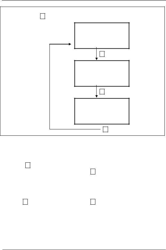
*1 Refer to Section 5.8 “How to enter alphanumeric characters”. With each pressing of F3 key, method of inputting backsight is changed.
1.Use recorded point
2.Enter coordinate directly
3.Enter angle directly
BACKSIGHT
PT#
INPUT LIST NE/AZ ENT
F3 NE/AZ
N-> |
0.000 m |
E:0.000 m
INPUT --- AZ ENTER
F3 AZ
BACKSIGHT
H(B) = 120°30′20″
INPUT --- PT# ENTER
F3 PT#
Example: Setting instrument point coordinates directly
Operation procedure |
Operation |
|
|
Display |
|
|
|
|
|
|
|
|
|
|
|
Press the F2 (BACKSIGHT) key from |
|
|
BACKSIGHT |
|
|
|
|
the Layout menu 1/2. |
F2 |
|
PT# |
|
|
|
|
|
|
|
|
|
|
|
|
The previous data is shown |
|
|
INPUT |
LIST |
NE/AZ |
ENT |
|
|
|
|
|
||||
|
|
|
|
|
|
|
|
|
|
|
|
|
|
|
|
|
|
|
N-> |
|
0.000 |
m |
|
Press the F3 (NE/AZ) key |
F3 |
|
E: |
|
0.000 |
m |
|
|
|
|
|
|
|
||
|
|
|
INPUT |
--- |
PT# ENTER |
|
|
|
|
|
|
|
|
|
|
101
PDF "pdfFactory Pro" www.fineprint.com.cn

|
|
|
|
|
|
|
|
Press the F1 (INPUT) |
key |
and enter |
F1 |
|
BACKSIGHT |
|
|
coordinate value. Press the |
F4 |
(ENT) key. |
Enter coord. |
|
H(B) = 120°30′20″ |
|
|
|
|
|
|
||||
*1 2 |
|
|
F4 |
|
>Sight? |
[YES] [NO] |
|
|
|
|
|
|
|||
|
|
|
|
|
|
||
|
|
|
|
|
|
|
|
Sight the backsight point |
|
|
Sight BS |
|
|
|
|
|
|
|
|
|
|
|
|
|
|
|
|
|
|
|
|
|
|
|
|
|
LAYOUT |
1 / 2 |
|
Press the F3 (YES) key |
|
|
F3 |
|
F1 OCC. PT |
INPUT |
|
The display returns to the layout menu 1/2. |
|
F2 BACKSIGHT |
|
||||
|
|
|
|||||
|
|
|
|
|
F3 LAYOUT |
P↓ |
|
|
|
|
|
|
|
|
|
*1 Refer to Section 5.8 “How to Enter Alphanumeric characters”.
*2 It is possible to record the coordinate value. Refer to chapter 15 “Basic Setting”.
13.3 Executing A Layout
The following methods can be selected for executing a Layout:
1)Recalling points from internal memory by point number
2)Direct key input of coordinate values
Example setting: Recalling point from internal memory
Operation procedure |
|
Operation |
|
Display |
|
||||
|
|
|
|
|
|
|
|
|
|
|
|
|
|
LAYOUT |
|
1 / 2 |
|
||
|
|
|
|
F1 OCC. PT |
INPUT |
|
|||
|
|
|
|
F2 BACKSIGHT |
|
||||
Press the F3 (LAYOUT) key |
from the |
|
|
F3 LAYOUT |
|
P↓ |
|
||
F3 |
|
|
|
|
|
|
|
||
|
|
|
|
|
|
|
|||
layout menu 1/2. |
|
|
|
|
|
|
|||
|
|
|
|
|
|
|
|
|
|
|
|
|
|
|
|
|
|
|
|
|
|
|
|
LAYOUT |
|
|
|
|
|
|
|
|
|
PT# |
|
|
|
|
|
|
|
|
|
INPUT |
LIST |
NEZ ENTER |
|
||
|
|
|
|
|
|
|
|
|
|
102
PDF "pdfFactory Pro" www.fineprint.com.cn

|
|
F1 |
|
|
|
|
|
|
|
|
|
Press the F1 (INPUT) key, and enter PT# |
|
REFLECTOR HEIGHT |
|
|
|||||||
# |
|
INPUT |
|
|
|
|
|
|
|
||
*1) Press the F4 (ENT) key *2) |
|
Enter PT |
|
|
|
|
|
|
|
|
|
|
F4 |
|
R.HT |
0.000 |
m |
|
|
|
|||
|
|
|
|
|
|
||||||
|
|
|
|
INPUT |
|
--- |
|
--- |
ENTER |
|
|
|
|
|
|
|
|
|
|
|
|
|
|
Enter reflector height in the same way |
|
|
|
|
|
|
|
|
|
|
|
When the layout point is set, the instrument |
|
|
|
|
|
|
|
|
|
|
|
F1 |
|
CALCULATED |
|
|
|
|
|||||
|
|
|
|
|
|
|
|||||
will start layout calculation. |
|
|
HR 122°09′30″ |
|
|
||||||
HR: Calculated horizontal angle of the layout |
Enter R.HT |
|
HD |
|
245.777 |
m |
|
|
|||
point |
|
F4 |
|
ANGLE |
|
DIST |
|
--- |
--- |
|
|
|
|
|
|
|
|
||||||
|
|
|
|
|
|
|
|
|
|
|
|
|
|
|
|
|
|
|
|
|
|
|
|
HD: Calculated horizontal distance from the |
|
|
|
|
|
|
|
|
|
|
|
instrument to the layout point |
|
|
|
|
|
|
|
|
|
|
|
Collimate the prism, and press the |
F1 |
|
|
|
|
|
|
|
|
|
|
(ANGLE) key. |
|
|
|
|
|
|
|
|
|
|
|
PT# Layout point |
|
|
|
|
|
|
|
|
|
|
|
|
Collimate |
|
PT# |
LP - 100 |
|
|
|
||||
HR Measured (Actual) horizontal angle |
|
|
|
|
|
||||||
|
|
HR |
|
2°09′30″ |
|
||||||
|
|
|
|
|
|
||||||
dHR Horizontal angle to be turned to |
the |
|
|
|
22 |
° ′ ″ |
|
||||
|
|
F1 |
|
dHR |
|
39 |
30 |
|
|
||
layout point =Actual horizontal angle- |
|
DIST |
|
--- |
|
NEZ |
--- |
|
|||
|
|
|
|
|
|||||||
Calculated horizontal angle |
|
|
|
|
|
|
|
|
|
|
|
Correct direction when dHR=0º00ˊ00" |
|
|
|
|
|
|
|
|
|
|
|
Press the F1 (DIST) key |
|
|
|
HD*[r] |
|
|
|
|
< m |
|
|
HD: Measuring (Actual) horizontal distance |
|
|
|
dHD |
|
|
|
m |
|
|
|
|
|
|
dZ |
|
|
|
|
m |
|
|
|
dHD: Horizontal distance to be turned to the |
|
|
|
|
|
|
|
|
|||
|
|
MODE |
ANGLE |
NEZ |
NEXT |
|
|||||
layout point=Actual horizontal distance |
|
F1 |
|
|
|
|
|
|
|
|
|
|
|
|
|
|
|
|
|
|
|
||
-Calculated horizontal distance |
|
|
|
HD* |
|
|
245.777 m |
|
|||
dZ: Vertical distance to be turned to the layout |
|
|
dHD |
|
|
- 3.223 m |
|
||||
point =Actual vertical distance |
|
|
|
dZ |
|
|
|
- 0.067m |
|
||
-Calculated vertical distance |
|
|
|
MODE |
ANGLE |
NEZ |
NEXT |
|
|||
103
PDF "pdfFactory Pro" www.fineprint.com.cn

|
|
|
HD*[r] |
|
|
< m |
|
|||
|
|
|
dHD |
|
m |
|
||||
|
|
|
dZ |
|
|
|
m |
|
||
Press the F1 (MODE) key |
|
|
MODE |
ANGLE |
NEZ |
|
NEXT |
|
||
F1 |
|
|
|
|
|
|
|
|
|
|
|
|
|
|
|
|
|
|
|
||
The fine mode measuring starts. |
|
|
|
|
|
|
|
|
|
|
|
|
HD* |
|
244.789 m |
|
|||||
|
|
|
|
|
||||||
|
|
|
dHD |
- 3.213 m |
|
|||||
|
|
|
dZ |
|
- 0.047m |
|
||||
|
|
|
MODE |
ANGLE |
NEZ |
|
NEXT |
|
||
|
|
|
|
|
|
|
|
|
|
|
When the display value dHR, Dhd and DZ |
|
|
|
|
|
|
|
|
|
|
are equal to 0,the layout point is established |
|
|
|
|
|
|
|
|
|
|
*3 |
|
|
|
|
|
|
|
|
|
|
|
|
|
|
|
|
|
|
|
||
|
|
|
N: |
|
12.352 m |
|
||||
Press the F3 (NEZ) key |
F3 |
|
E |
|
34.286 m |
|
||||
The coordinate data is shown. |
|
Z |
|
1.5772 m |
|
|||||
|
|
|
|
|||||||
|
|
|
MODE |
ANGLE |
--- |
NEXT |
|
|||
|
|
|
|
|
|
|
|
|
|
|
|
|
|
LAYOUT |
|
|
|
|
|
|
|
Press the F4 (NEXT) key to set next layout |
F4 |
|
PT# |
|
|
|
|
|
|
|
|
|
|
|
|
|
|
|
|||
point PT# is automatically incremented. |
|
|
|
|
|
|
|
|
|
|
|
|
INPUT |
LIST |
NEZ |
ENTER |
|
||||
|
|
|
|
|||||||
|
|
|
|
|
|
|
|
|
|
|
|
|
|
|
|
|
|
|
|
|
|
*1 Refer to Section 5.8 “How to Enter Alphanumeric characters”.
*2 Point number could not be entered when data to comply with the coordinate value does not exist in the file.
*3 Cut & Fill display function is available. Refer to Chapter 15 “Basic Setting”.
13.4 Setting A New Point
New point is required, for example, when a layout point cannot be sighted from existing occupied points.
13.4.1 Side Shot Method
Set up the instrument at a known point, and measure the coordinate of the new points by the side shot method.
104
PDF "pdfFactory Pro" www.fineprint.com.cn

Operation procedure |
Operation |
|
|
|
Display |
|
|
||
|
|
|
|
|
|
|
|
|
|
|
|
|
LAYOUT |
|
|
|
1 / 2 |
|
|
|
|
|
F1 OCC.PT |
INPUT |
|
||||
|
|
|
F2 BACKSIGHT |
|
|
||||
Press the F4 (↓) key from the layout |
|
|
F3 LAYOUT |
|
P↓ |
|
|||
F4 |
|
|
|
|
|
|
|
|
|
|
|
|
|
|
|
|
|
||
menu 1/2 to get the layout menu 2/2. |
|
|
|
|
|
|
|
|
|
|
|
|
|
|
|
|
|
|
|
|
|
|
|
|
|
|
|
|
|
|
|
|
LAYOUT |
|
|
|
2 / 2 |
|
|
|
|
|
F1 SELECT |
A |
FILE |
|
|||
|
|
|
F2 NEW |
POINT |
|
|
|||
|
|
|
F3 GRID |
FACTOR P↓ |
|
||||
|
|
|
|
|
|
|
|
||
|
|
|
|
|
|
|
|
|
|
|
|
|
NEW |
POINT |
|
|
|
||
Press the F2 NEW POINT key |
F2 |
|
F1 SIDE SHOT |
|
|
|
|||
|
|
|
F2 : RESECTION |
|
|
||||
|
|
|
|
|
|
|
|
||
|
|
|
SELECT |
A |
FILE |
|
|
||
Press the F1 (SIDE SHOT key |
F1 |
|
FN ___________ |
|
|
||||
|
|
|
|
|
|
|
|
||
|
|
|
INPUT |
|
LIST |
--- |
ENTER |
|
|
|
|
|
|
|
|
||||
|
|
|
COORDDATA |
/C0352 |
|
||||
Press the F2 (LIST) key to display the |
F2 |
|
->*DATA |
/C0228 |
|
|
|||
list of coordinate data file *1) |
|
SATADDATA |
/C0080 |
|
|||||
|
|
|
|||||||
|
|
|
--- |
SRCH |
|
--- |
ENTER |
|
|
|
|
|
|
|
|
|
|||
|
|
|
|
|
|
|
|||
Scroll file list by pressing [▲] or [▼] |
|
|
*DATA |
/C0228 |
|
|
|||
[▲]or[▼] |
|
->SATADDATA |
/C0080 |
|
|||||
key and select a file to use *2 3 |
|
|
KLLLSDATA |
/C0085 |
|
||||
|
|
|
|
||||||
|
|
|
--- |
SRCH |
|
--- |
ENTER |
|
|
|
|
|
|
|
|
|
|||
|
|
|
|
|
|
|
|
|
|
Press the F4 (ENTER) key. |
|
|
SIDE SHOT |
|
|
|
|||
F4 |
|
PT#: |
|
|
|
|
|
||
The file will be set. |
|
|
|
|
|
|
|
|
|
|
|
|
|
|
|
|
|
|
|
|
|
|
INPUT |
|
SRCH |
--- |
ENTER |
|
|
|
|
|
|
|
|
|
|
|
|
105
PDF "pdfFactory Pro" www.fineprint.com.cn

|
|
|
|
|
|
|
|
Press the F1 (INPUT)key, and enter new |
F1 |
|
REFLECTOR |
HEIGHT |
|
||
|
INPUT |
|
|
|
|
||
point name. *4 |
Enter PT# |
|
|
|
|
|
|
|
R.HT : |
|
0.000 |
m |
|
||
Press the F4 (ENT) key. |
F4 |
|
|
|
|||
|
INPUT |
--- |
--- ENTER |
|
|||
|
|
|
|
||||
|
|
|
|
|
|
||
|
|
|
|
|
|
||
|
|
|
|
|
|
|
|
|
F1 |
|
REFLECTOR |
HEIGHT |
|
||
|
|
|
|
|
|
|
|
Enter reflector height in the same way. |
Enter RHT |
|
INPUT |
|
|
|
|
|
R.HT : |
|
1.356 |
m |
|
||
|
F4 |
|
|
|
|||
|
|
>Sight ? |
|
[YES] |
[NO] |
|
|
|
|
|
|
|
|||
|
|
|
|
|
|
||
|
|
|
|
|
|
|
|
|
|
|
H R: |
2°09′30″ |
|
||
|
|
|
HD* |
|
<m |
|
|
|
|
|
VD |
|
|
m |
|
Collimate the new point, and press the |
|
|
>Measuring… |
|
|
|
|
|
|
|
|
|
|||
Collimate F3 |
|
< complete > |
|
|
|||
F3 (YES) key. Distance measuring starts. |
|
|
|
|
|
|
|
|
|
|
|
|
|
|
|
|
|
|
|
|
|
||
|
|
|
N: |
12.352 m |
|
||
|
|
|
E |
34.286 m |
|
||
|
|
|
Z |
1.5772 m |
|
||
|
|
|
>REC ? |
|
[YES] |
[NO] |
|
|
|
|
|
|
|
|
|
Press the F3 (YES) key *5) |
|
|
|
|
|
|
|
The name and coordinate value are stored |
|
|
SIDE SHOT |
|
|
||
into COORD DATA |
F3 |
|
PT#: |
NP-101 |
|
|
|
|
|
|
|
|
|
|
|
The input menu for next point is displayed |
|
|
INPUT |
SRCH |
--- |
ENTER |
|
PT# is automatically incremented. |
|
|
|
||||
|
|
|
|
|
|
|
|
|
|
|
|
|
|
|
|
*1 If you want to input file name directly, press the F1 (INPUT) key and enter a file name. *2 When a file has been selected already the mark * is indicated on left of current file name. For the file discrimination mark refer to Chapter 14.3 “FILE MAINTENANCE”.
*3 Data in a file shown with arrow can be searched by pressing F2 (SRCH) key. *4 Refer to Section 5.8 “to Enter Alphanumeric characters”.
*5 An error will be displayed when the internal memory is full.
106
PDF "pdfFactory Pro" www.fineprint.com.cn
