

3231
.pdfIssue № 1 (49), 2021 |
ISSN 2542-0526 |
equipment in question is higher by an average of 5%, which signals the efficiency of employing corrugated plates with spherical recesses located according to the linear law.
Heat transfer coefficient, K
Average temperature pressure, t
Fig.: 4. Graph of the dependence of the heat transfer coefficient on the temperature head: 1 is a plate heat exchanger with corrugated plates; 2 is an intensified plate heat exchanger with modified corrugated plates
Conclusions
1. The above method of intensification of heat exchange processes, i.e., the application of sphericaldepressionsaccordingtoalinearlaw,leadstoanincreaseintheturbulizationofthecoolant. 2. It has been experimentally established that spherical depressions with a radius of 0.35 mm retain the plate rigidity and cause the appearance of a vortex zone, which promotes more efficient mixing of the coolant.
3.The comparison of the two plate heat exchangers confirms the advantage of employing modified corrugated plates.
4.The height of the turbulization zone was 30% of the accepted radius of the spherical deepening.
5.A high value of the heat transfer coefficient will cause a decrease in the cost of heat exchange equipment, as well as in overall dimensions (metal consumption) and an increase in service life.
References
1. Alifanov O. M., Artyukhin E. A., Nenarokomov A. V. Obratnye zadachi v issledovanii slozhnogo teploobmena [Inverse problems in the study of complex heat transfer]. Moscow, Yanus-K Publ., 2009. 300 p.
51

Russian Journal of Building Construction and Architecture
2.Vygodskii M. Ya. Spravochnik po vysshei matematike [Handbook of higher mathematics]. Moscow, Fizikomatematicheskaya literature Publ., 2010. 890 p.
3.Gukhman A. A. Intensifikatsiya konvektivnogo teploobmena i problema sravnitel'noi otsenki teploobmennykh poverkhnostei [Intensification of convective heat transfer and the problem of comparative evaluation of heat exchange surfaces]. Teploenergetika, 1977, No. 4, pp. 5––8.
4.Zhidkov A. V. Primenenie sistemy ANSYS k resheniyu zadach geometricheskogo i konechno-elementnogo modelirovaniya [Application of the ANSYS system to solving problems of geometric and finite element modeling]. Nizhnii Novgorod, Nizhegorodskii gosudarstvennyi universitet im. N. I. Lobachevskogo Publ., 2006. 115 p.
5.Zhukauskas A. A. Konvektivnyi perenos v teploobmennikakh [Convective transfer in heat exchangers]. Moscow, Nauka Publ., 1982. 472 p.
6.Kaplun A. B., Morozov E. M., Olfer'eva M. A. ANSYS v rukakh inzhenera. Prakticheskoe rukovodstvo
[ANSYS in the hands of an engineer. Practical guide]. Moscow, Librokom Publ., 2015. 272 p.
7.Kudinov V. A., Kartashov E. M., Stefanyuk E. V. Teplotekhnika [Teplotekhnika]. Moscow, Abris Publ., 2014. 424 p.
8.Kudinov I. V. Matematicheskoe modelirovanie gidrodinamiki i teploobmena v dvizhushchikhsya zhidkostyakh [Mathematical modeling of hydrodynamics and heat transfer in moving liquids]. Saint Petersburg, Lan' Publ., 2015. 208 p.
9.Kushchev L. A., Nikulin N. Yu., Ryapolov A. N. [Modern methods for improving the efficiency of heat supply systems]. Povyshenie effektivnosti stroitel'nogo proizvodstva za schet primeneniya novykh materialov i innovatsionnykh tekhnologi i: sb. tr. Vseros. nauch.-prakt. konf. [Improving the efficiency of the construction production through the use of new materials and innovative technologies: collection of works]. Ryazan', 2013. Pp. 113––118.
10.Makarov A. N. Teploobmen v elektrodugovykh i fakel'nykh metallurgicheskikh pechakh i energeticheskikh ustanovkak [Heat Transfer in electric arc and flare metallurgical furnaces and power plants]. Saint Petersburg Lan' Publ., 2014. 384 p.
11.Marinyuk B. Raschety teploobmena v apparatakh i sistemakh nizkotemperaturnoi tekhniki [Calculations of heat transfer in apparatuses and systems of low-temperature equipment]. Moscow, Mashinostroenie Publ., 2015.
272p.
12.Kushchev L. A., Savvin N. Yu., Feoktistov A. Yu. Plastina teploobmennika [Heat exchanger Plate]. Patent RF, no. 2020114112, 2020.
13.Rudskoi A. I., Lunev V. A. Matematicheskoe modelirovanie gidrodinamiki i teploobmena v dvizhushchikhsya zhidkostyakh [Mathematical modeling of hydrodynamics and heat transfer in moving liquids]. Saint Petersburg Lan' Publ., 2015. 208 p.
14.Savvin N. Yu., Nikulin N. Yu. [High-Efficiency heat exchanger for housing and communal services]. Sbornik nauchnykh trudov v 9 ch. [Collection of scientific papers in 9 hours]. Novosibirsk, NGTU Publ., 2019. Pp. 256––262.
15.Savvin N. Yu., Nikulin N. Yu. [Application of heat exchangers in centralized heat supply]. Molodezh' i nauchno-tekhnicheskii progress : XIII mezhdunarodnaya prakticheskaya konferentsiya studentov, aspirantov i molodykh uchenykh [Youth and scientific and technical progress : XIII international practical conference of students, postgraduates and young scientists]. Gubkin, 2020. Pp. 302–304.
52
Issue № 1 (49), 2021 |
ISSN 2542-0526 |
16.Savvin N. Yu. [Improving the design of a plate heat exchanger]. Mezhdunarodnaya nauchno-tekhnicheskaya konferentsiya molodykh uchenykh [International scientific and technical conference of young scientists]. Belgorod, BGTU im. V. G. Shukhova Publ., 2020. Pp. 2240––2244.
17.Gulenoglu. C., Akturk F., Aradag S., Sezer Uzol N., Kakac S. Experimental comparison of performances of three different plates for gasketed plate heat exchangers. International Journal of Thermal Sciences, 2014, no. 75, pp. 249––256.
18.Gupta A. K., Kumar P., Sahoo R. K., Sahu A. K., Sarangi S. K. Performance measurement of plate fin heat exchanger by exploration: ANN, ANFIS, GA, and SA. Journal of Computational Design and Engineering, 2016, no. 4, pp. 60––68.
19.Huikun C., Lijun S., Yidai L., Zeju W. Numerical and experimental study on the influence of top bypass
flow on the performance of plate fin heat exchanger. Applied Thermal Engineering, 2018, no. 146, pp. 356––363.
20.Kexin X., Robin S., Nan Z. Design and optimization of plate heat exchanger networks. Computer Aided Chemical Engineering, 2017, no. 40, pp. 1819––1824.
21.Wagh Р., Pople M. U. Optimization of a Shell and Tube Condenser using Numerical Method. Int. Journal of Engineering Research and Applications, 2015, vol. 7, pp. 9––15.
53

Russian Journal of Building Construction and Architecture
DOI10.36622/VSTU.2021.49.1.005 UDC621.6.036
A. L. Shuraits1, A. V. Birykov2, А. Р. Usachev3
DEVELOPMENT OF A CALCULATION METHOD
FOR TWO-STAGE NATURAL GAS PURIFICATION PLANTS
FROM MECHANICAL IMPURITIES
Giproniigaz PLC 1, 2
Russia, Saratov
Yuri Gagarin State Technical University of Saratov 3
Russia, Saratov
1 D. Sc. in Engineering, Prof., Director General, tel.: (8452)74-95-95, e-mail: shuraits@niigaz. ru 2 PhD, Director of the Research Center, tel.: (8452) 74-94-15, e-mail: Biryukov@niigaz.ru
3 D. Sc. in Engineering, Prof. of the Dept. of Heat and Gas Supply, Ventilation, Water Supply and Applied Fluid Dynamics, tel.: (8452) 51-50-18, e-mail: usachev-ap@mail.ru
Statement of the problem. Currently, there is no methodology for calculating the degree of clogging of a multilayer filter cartridge taking into account the prevention of deposition of mechanical impurities in the gap between the coarse and fine filter cylindrical filter cartridges. In this regard, the development of such a technique is an urgent task.
Results. In this paper, we propose a calculation method for determining the average integral degree of clogging of multilayer cylindrical filter cartridges with mechanical impurities and pressure loss on them which take into account the prevention of sedimentation of mechanical impurities in the gap between the coarse and fine filter cartridges.
Conclusions. The results obtained make it possible to determine the pressure loss and the average integral degree of clogging of the multilayer filter cartridge depending on the decrease in the living cross-section of all filter meshes in the process of clogging and to prevent the deposition of solids in the gap between the coarse and fine filter cartridges.
Keywords: calculation procedure, mechanical impurities, clearance, cylindrical filter cartridges, coarse and fine purification, natural gas, two-stage purification installation, prevention of deposition.
Introduction. Reliable operation of high-precision modern high-performance equipment for reducing the pressure of natural gas is achieved through the use of two-stage gas purification from mechanical impurities [11]. The analysis and experience of gas distribution organizations show that about 70 % of mechanical particles in their total balance are deposited on coarse cylindrical filter cartridges (CPF) and only 30 % –– on fine CPF [2, 3, 6].
© Shuraits А. L., Biryukov А. V., Usachev А. P., 2021
54
Issue № 1 (49), 2021 |
ISSN 2542-0526 |
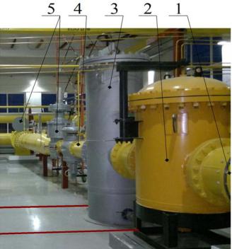
An example of a reduction line of the head gas reduction stations (GRS) with a total capacity of 500 thousand m3/h with two-stage cylindrical setups (TCS) installed on it for coarse and fine purification of high throughput is shown in Fig. 1.
Fig. 1. TCS with coarse and fine purification hcapacity:
1, 4 are inlet and outlet branch pipes; 2, 3 are cylindrical filters with coarse and fine purification capacity; 5 is gas regulating equipment
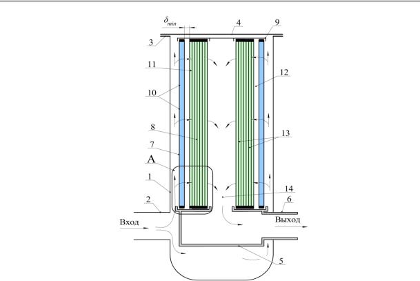
The process of two-stage purification of natural gas from mechanical impurities was previously described in [1, 5––10, 14––21]. Thus, the principle of reducing capital and metal consumption, set forth in [9], is incorporated in the design of the TCS and involves placing in the internal volume of one housing coaxially installed CPFs of coarse purification from a single-layer mesh and fine purification from a multi-layer cloth located at the minimum permissible distance where the degree of clogging of the coarse filtering mesh does not increase compared to when the actual distance δph between the filtering elements is δf δmin (Fig. 2).
However, in [1, 5––10, 14––21] there is no method for calculating the degree of clogging of the CPF at any moment of operation considering the conditions that prevent the deposition of mechanical impurities in the gap between the CPF of coarse and fine purification. Therefore the development of such a calculation method is relevant.
55
Russian Journal of Building Construction and Architecture
Inlet |
|
Outlet |
Fig. 2. Diagram of a device with a coarse and fine purification CPF set up in the volume of one complex: 1 –– vertical cylindrical body; 2, 6 –– inlet and outlet branch pipes; 3, 4 –– flange and filter cover; 5 –– glass; 7, 8 –– CPF for coarse and fine purification; 9 –– cover for CFF 7 and 8;
10 –– cells of CPF for coarse purification; 11 –– the first in the direction of the gas flow filtering layers of the CPF of fine purification; 12 –– gap between the CPF of coarse and fine purification;
13 –– filtering layers of fine purification CPC following after the first ones; 14 –– space for clean gas outlet area
The objective of the study is to develop a calculation method for identifying the degree of clogging of multilayer filter cloths of coarse and fine purification with mechanical impurities and the value of pressure losses on cylindrical filter cartridges.
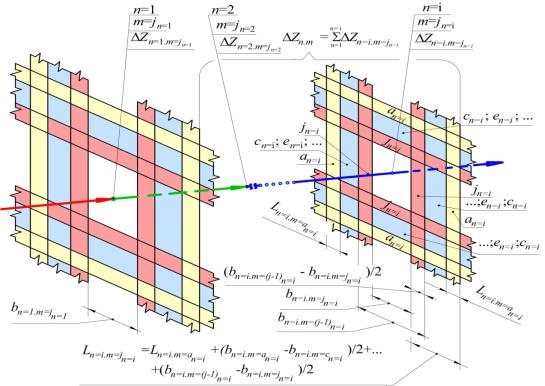
1.Development of a calculation method for identifying the degree of clogging of coarse and fine filter purification. In general, a multilayer filtering fabric is made of n nets, one after the other. The network gas with the maximum content of mechanical impurities at a constant design flow rate V = const is cleaned in several meshes n (Fig. 3) sequentially performed along the gas flow, with square cells and a standard size equal to mn. The mesh number n in the row will change in the range n = 1; 2; 3; …, i. The number of the standard size of the cells of each mesh n in a row in the process of clogging changes to the values mn = an, cn, en,…, jn. In the process of clogging, mechanical impurities of a smaller size are deposited on each first mesh, thus each subsequent mesh in the direction of the gas flow has a smaller initial and subsequent sizes compared to the previous mesh.
56
Issue № 1 (49), 2021 |
ISSN 2542-0526 |
Fig. 3. Scheme of successively located along the gas flow mesh fragments with a number in the range n = 1; 2; 3; …, i and the standard size of the mesh cell equal to mn:
n = 1; 2; 3; …, i is the mesh number n in the row;
mn = аn, сn, en, jn is the number of the standard size of the cells of each mesh n in a row during its clogging; Ln=i. m=jn=i is the distance between two adjacent square cells of each next mesh n in the direction of gas flow in the process of clogging; bn=i. m=jn=i is the width of square cells in the light of each next mesh n in the direction of gas flow in the process of clogging; ∆Zn=i. m=jn=i is the pressure loss when the gas passes through the mesh n in the direction of the gas flow during clogging
The distance between two adjacent square cells of each subsequent mesh Ln=i.m= jn=i in the
direction of gas flow (Fig. 3) has a lower initial and subsequent value compared to the previous mesh Ln=i-1.m= jn=i-1 , i.e.,
Ln=i-1.m= jn=i-1 > Ln=i.m= jn=i .
At the initial moment, the relative value of the net cross-section
b2 |
/ bn=i.m=аn=i+Ln=i.m=аn=i 2 , |
n=i.m=аn=i |
|
located at the point n=i in the direction of the gas flow, corresponds to the degree of its clog-
ging by mechanical impurities θn=i.m=аn=i equals zero.
With m=j as as a contaminated element located at the point n=i in the direction of gas flow (Fig. 3), a filter element with a cell having a smaller size is conventionally taken
57

Russian Journal of Building Construction and Architecture
(at m = j) compared to the previous size bn=i.m=(j-1)n=i (at m = (j-1)n=i). A reduction of any previous size of the mesh cell located at point n=i in the direction of the gas flow, with bn=i.m=(j-1)n=i to the subsequent bn=i.m= jn=i during its clogging is presented as an increase in the distance between the mesh cells to the value:
m= j
Ln=i.m= jn=i Ln=i.m=an=i (bn=i.m=(j-1)n=i - bn=i.m= jn=i ) . (1) m=1
The dependence for identifying the total pressure loss [12] when gas passes through a series of meshes n=1; 2; 3; ..., i sequentially located one after another (Fig. 3) along its course when each subsequent mesh n has a smaller initial and subsequent sizes compared to the previous one is written as:
|
|
|
V 2 |
b |
|
+ L |
|
m= j |
(b |
|
- b |
n=i ) |
4 |
|
|||
n=i |
|
|
n=i |
n=i |
+ |
n=i |
|
|
|||||||||
|
|
|
|
|
n=i.m=a |
|
n=i.m=a |
|
m=1 |
|
n=i.m=(j-1) |
|
n=i.m= j |
|
|
|
|
Zn.m |
n=i.m= j |
|
|
|
|
|
|
|
|
|
|
|
г , (2) |
||||
|
|
|
|
|
|
|
|
|
|
|
|||||||
|
|
|
|
4 |
|
|
2 |
|
|
|
|
|
|||||
n=1 |
|
n=i |
|
|
|
|
|
bn=i.m= jn=i × F 2 g |
|
|
|
|
|
||||
|
|
|
|
|
|
|
|
|
|
|
|
||||||
where n=i.m= j |
is the coefficient of local resistance of the mesh [4] at the point n = i in the |
||||||||||||||||
|
n=i |
|
|
|
|
|
|
|
|
|
|
|
|
|
|
|
|
direction of the gas flow for m= jn=I which is typical of the current size bn=i.m= jn=i , caused by its being polluted with mechanical impurities; V is the capacity of the filtering device at excess gas pressure at the inlet to the TCS numerically equal to the calculated gas flow rate [11], m3/sec; bn=i.m=an=i is the value of the nominal initial cell size of a clean mesh in the light, not contaminated with mechanical impurities which is located at the point n=i in the direction of the gas flow for m= an=i (Fig. 3), m; Ln=i.m= jn=i is the value of the nominal initial distance between mesh cells in the light (Fig. 3) at the point n=i in the direction of the gas flow for m=jn=i, m; bn=i.m=(j-1)n=i ,bn=i.m= jn=i is the previous and next dimensions of the square cell of the filtering mesh located at the point n=i in the direction of the gas flow clogged with mechanical impurities, m; г is the density of gas passing through the mesh cells at the excess pressure of the TCS inlet, kg/m3; g is the value of the acceleration of gravity equal to 9,8 m/sec2.
The average integral degree of clogging of the filter cloth (as a series of meshes) in fractions of one can be identified by means of calculating the total degree of clogging of all meshes and then dividing the resulting value by the number of meshes n =i:
58
Issue № 1 (49), 2021 |
ISSN 2542-0526 |
|
|
|
b2 |
|
|
- |
|
|
|
|
|
bn=i.m=2 |
jn=i |
|
|
|
|
|
|||||
|
|
|
n=i.m=аn=i |
|
|
|
|
|
|
|
|
|
|
|
|
|
|
|
|
||||
|
|
b |
+L |
2 |
|
|
|
|
|
|
m= jn |
|
|
|
2 |
|
|
||||||
|
|
|
n=i.m=аn=i |
n=i.m=аn=i |
|
|
|
b |
+L |
|
+ |
|
b |
-b |
|
|
|
|
|||||
|
n=i |
|
|
|
|
|
|
|
|
|
|
||||||||||||
|
|
|
|
|
n=i.m=an=i |
n=i.m=an=i |
|
|
|
n=i.m=(j-1)n=i |
n=i.m= jn=i |
|
|
||||||||||
|
|
|
|
|
|
|
|
|
|
|
|
|
|
m=аn |
|
|
|
|
|
. |
|
||
|
|
|
|
|
|
|
|
|
|
|
|
|
|
|
|
|
|
|
|||||
|
n=1 |
|
|
|
|
|
|
b2 |
|
|
|
|
|
|
|
|
|
|
|
||||
|
|
|
|
|
|
|
|
|
|
|
|
|
|
|
|
|
|
|
|||||
|
|
|
|
|
|
|
|
|
n=i.m=аn=i |
|
|
|
|
|
|
|
|
|
|||||
|
|
|
|
|
|
|
|
|
b |
+L |
|
2 |
|
|
|
|
|
|
|
|
|||
|
|
|
|
|
|
|
|
|
n=i.m=аn=i |
n=i.m=аn=i |
|
|
|
|
|
|
|
|
|
||||
|
|
|
|
|
|
|
|
|
|
|
|
|
|
|
|
|
|
|
|
|
(3) |
||
θср.n.m = |
|
|
|
|
|
|
|
|
|
|
|
|
|
|
|
|
|
|
|
|
|
||
|
|
|
|
|
|
|
|
|
n=i |
|
|
|
|
|
|
|
|
|
|
||||
|
|
|
|
|
|
|
|
|
|
|
|
|
|
|
|
|
|
|
|
|
|
|
|
Here, at any moment of operation with m =jn=i, the relative value of the net cross section corresponds to a certain extent of its clogging by mechanical impurities. The formulas (2) and (3) are also valid for identifying the pressure loss and the mean integral degree of clogging of one filter mesh, e.g., as is the case for coarse CPF if the value n = 1 is taken.
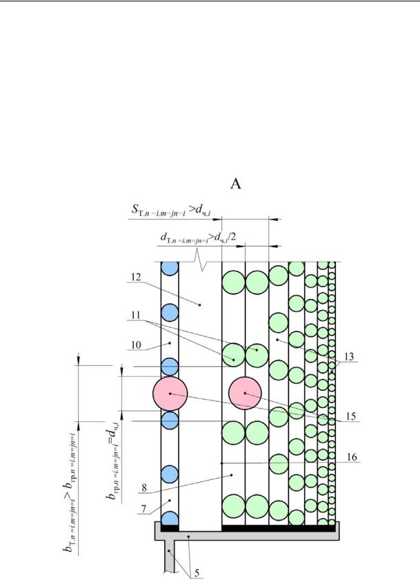
2. Development of a calculation method to prevent the deposition of solid particles in the gap between the CPF of coarse and fine purification. An integral part of the methodological provisions for identifying the degree of clogging of a multilayer filter cartridge is the development of conditions to prevent the deposition of mechanical impurities in the lower part of the gap 12 (Fig. 2) between the cylindrical filter cartridges of coarse and fine purification. In order to do this, the following ratio of the mesh sizes of coarse and fine CPF meshs was set forth (Fig. 2 and fragment A in Fig. 4):
1. Uncontaminated coarse filter element 7 made of woven metal mesh, which has 10 cells, with a nominal initial clear size bгр.n=1.m=an=1 (Fig. 4), at the initial moment of operation passes through solid particles 15 with a maximum diameter dч, equal to the size of the mesh bгр.n=1.m=an=1CPF 7 coarse purification. I.e.,
dч bгр.n=1.m=an=1. |
(4) |
2. An uncontaminated fine filter element 8 is made of a multi-layer fabric consisting of a number of meshes arranged one after the other, inside which solid particles will settle. In this case,
at least the first layers 11 in the direction of the gas flow have cells with a size bт.n=1.m=an=1 larger than the maximum diameter of solid particles dч. I.e.,
bт.n=1.m=an=1 dч. |
(5) |
The diameter of 11 fibers of these first uncontaminated layersdт.n=1.m=an=1, laid one after the other, should be more than half the maximum diameter dч/2 of solid particles 15, i.e.:
59
Russian Journal of Building Construction and Architecture
dт.n=1.m=an=1 dч /2. |
(6) |
The thickness Sт.n 1.m=an 1 of the first two layers in the direction of gas flow exceeds the maximum diameter dч of solid particles 15, i.e.:
Sт.n 1.m=an 1 dч. |
(7) |
For each subsequent layer 13, the cell sizes are reduced, and the last layer has the minimum cell sizes. The operation of the CPF for coarse and fine purification, conducted according to the recommendations laid down in formulas (4)––(7), is performed in the following way.
Fig. 4. Diagram showing the aspect ratio at which the settling of solids is prevented
in the lower part of the gap between the coarse and fine CPF, the capacity of the CPF is preserved. The geometric parameters of the meshes are shown on the enlarged lower part of the coarse and fine CPF. Positions1––14 are the same as in Fig. 2; 15 is the maximum diameter of a solid particle
60