

книги / Разработка нефтяных и газовых месторождений. Ч. 2
.pdfWhen minimum bottomhole flowing pressure Рmin bhf, it is necessary to determine minimum bottomhole pressure Рmin bh for the given well operation considering constraints mentioned in Section 4.
If |
Рmin bhf< Рmin bh< Рf , |
(19) |
flowing well operation should be selected (Рbh ≥ Рmin bh).
If |
Рmin bh< Рmin bhf < Рf , |
(20) |
Flowing operation at Рbh ≥ Рbhf or artificial lift at (Рbh > Рmin bh) < Рmin bhf should be selected.
In the latter case, if condition (20) is met, well flow rate under artificial lift (qaf) is higher than flowing well flow rate (qf).
Maximal flow rate under flowing well operation:
Qf = PF (Рf – Рbhf), |
(21) |
under artificial lift: |
|
qal = PF (Рf – Рmbh) |
(22) |
at Рmin bh< Рmin bhf , well flow rate under artificial lift is higher than flowing well flow rate qal > qf .
In selecting lift methods under condition (20), it is necessary to consider economics reasoning from the point of high profit.
Type of artificial lift should be selected considering company’s experience and fluid lift cost per unit. As illustration, fig. 7 shows a conditional relationship between fluid lift cost per unit and sucker rod pumping well operation, and fluid lift cost per unit and electric centrifugal pumping well operation.
Fig. 7. Relationship between well flow rate and fluid lift cost per unit
21
From the above fig. 7, we can see that if well flow rate is lower than 20 m3/d, sucker rod pumping should be selected, and electric centrifugal pump if well flow is higher.
5.2. Well Operating Practice Analysis and Optimization
For each lift method, it is necessary to select wellhead equipment and equipment running conditions. Under flowing well operation, tubing of definite diameter (outside diameter 48, 60, 73, 89, and 114 mm, respectively, 2; 2.5; 3.0; 3.5; and 4 inches) should be used as wellhead equipment. In addition, wellhead should be equipped with choke.
Under sucker rod pumping, well is equipped with sucker rod plunger pump which is brought into operation by sucker-rod string. Fluid lifts along tubing. Wellhead is equipped with conventional pumping unit with drive motor and gear.
Under electric centrifugal pumping, well is equipped with submersible unit comprised of centrifugal multi-stage pump and electric motor with protector (seal section). Submersible electric motor is power supplied by special electric cable from surface. Fluid lifts along tubing string. Wellhead is equipped with transformer and control panel.
Wellheads of all production wells should be sealed with special equipment that is used for directing well product to the gathering system.
When selecting equipment and equipment running conditions, it is necessary to determine pump setting depth, pump technical data (pump type, plunger diameter for sucker rod pumps, rated pumping capacity and head of electric centrifugal pumps and so on). Equipment should be selected so that to provide high delivery rate under sucker rod pumping. And under electric centrifugal pumping, pump must operate within effective range with small delivered head hold-up.
Delivery rate of sucker rod pump is ratio of actual delivery to theoretical delivery: α = qa/qt . (23)
Actual delivery (well flow rate) qa is measured on the surface (m3/d), and theoretical delivery:
Qt = 1440 · Fpl · Sо · n, |
(24) |
22
where Fpl pump plunger cross sectional area (by outside diameter); Sо is sucker rod hanger center stroke length; and n is number of double strokes of sucker rod hanger center per minute.
On the other hand, delivery rates are:
α = β·γ·δ·χ, (25) where γ is factor considering elastic deformation of sucker rod string and tubing string under operation; β· is volumetric efficiency of pump; ·δ· is oil shrinkage factor (oil volume change on surface in relation to oil volume in pump); and χ is fluid leakage factor in pump and tubing string.
Each of the above factors under the given well conditions depends on pump setting depth: the deeper pump setting, the higher β factor (as free gas content of gas-fluid mixture flowing to pump becomes lower) due to pump intake pressure increase, but other factors become lower.
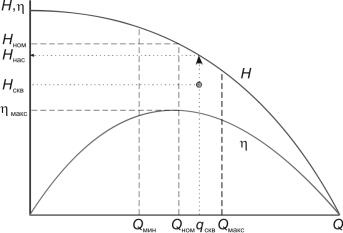
Electric centrifugal pump performance is shown in fig. 8.
Fig. 8. Electric Centrifugal Pump Performance
Q is pump delivery; H is developed head; and Η is lifting efficiency. In selecting electric centrifugal pump, it is necessary to consider that:
a) well flow rate qw shall be within the range:
Qmin ≤ qw ≤ Qmax |
(26) |
b) pump head to be developed under operation in well (Нw) |
|
Нw ≤ Нs, |
(27) |
where Нs is pump head developed under Q = qw. |
|
23 |
|

If the head of pump to be selected shall differ from Hp on 15…20 %, is necessary to control (reduce) Нp by removing stages or equip wellhead with choke.
5.3 Gas Well Operating Practice Engineering
Gas well produces gas and gas condensate. According to formula (12) and twoterm gas influx formula (13), well flow rate becomes higher if bottomhole pressure becomes lower. However, some factors affect bottomhole pressure Рbh decrease, and, consequently, gas well flow rate. Such factors include: potential drowning (well waters out), potential reservoir destruction on borehole walls within the pay zone, sanding-up and other. Considering the dominant factor that constrains gas withdrawal through this or that well, there are the following gas well drive mechanisms:
1. Constant borehole wall pressure gradient:
dP |
= const, |
(28) |
|
|
|
||
dr |
r=r |
|
|
|
|
c |
|
where dP is pressure change within surface element dr; r is distance from borehole axis.
Such drive is established if there is potential reservoir destruction in borehole environment. In case of reservoir destruction, large amount of small particles of broken rock (usually, sand) ingresses borehole together with gas, and well sanding-up can take place under condensed moisture and sand presence in well. Such sand plugs can completely cover the cross section of production string. Reservoir destruction causes caving around the well within the pay zone, and it can result in production string buckling in the bottomhole.
Pressure gradient under well operation should be maintained so that to prevent cemented rock destructing around the well. It is next to impossible to satisfy condition (28) in real well, so pressure gradient can be considered as finite differences (∆Р/∆r) = const, under assumption that ∆r = 1 cm. But even in such case it is impossible to control that parameter under well operation.
2. In case of reservoir destruction, drive ∆Рf = const is established instead of drive
∆Р/∆r = const, as well as if bottom water or edge water inflow is possible.
24
Water inflow causes some problems in well operation. Bottomhole accumulated water can entry the gas-saturated portion of reservoir and reduce gas phase permeability of rock, and, consequently, gas influx. Water lifting requires additional energy. Water content in gas flow enhances potential sanding-up or gas-hydrate plug forming. Water column in well makes bottomhole pressure higher and gas influx lower.
Underbalance (∆Рf) should be so that to prevent water inflowing.
3.Drive Рbh = const. It is established in cases: a) potential condensate dropout from gas in bottomhole zone; b) potential condensate dropout from gas in well; and c) potential crystalline hydrates formation. It is known that condensate (hydrocarbons, heavier than gas, dissolved in light gas and transferred to liquid state) is formed under temperature and pressure decrease. Condensate can be formed under definite pressure at gas temperature in bottomhole. If bottomhole pressure is lower than such condensate forming pressure, condensate can be formed in bottomhole formation zone, and gas phase permeability in bottomhole formation zone becomes lower and a part of condensate remains unrecovered because hydrocarbon recovery factor for liquid is always lower than that for gas. The part of condensate will flow to well and make gas flowing conditions worse.
Thus, it is necessary to maintain level of bottomhole pressure so that to prevent condensate forming within bottomhole formation zone.
And it should be noted that condensate formation in well (wellhead pressure is lower than due point pressure) can be characterized by the following regularity: the higher bottomhole pressure, the closer to wellhead condensate is formed.
4.Constant wellhead pressure (Рwh = const) drive. Such drive should be established considering conditions for gas transportation to consumer (or to the first compressor station in gas main pipeline), and condensate forming in well. If it is required to prevent condensate forming under well operation, wellhead pressure shall not be lower than dew point pressure.
5.Constant gas lift bottomhole velocity (Vbh = const) drive. It should be established if mechanical impurities (solid phase particles) ingress well together with gas inflow. Sand and other particles from rock matrix carried by gas inflow must be withdrawn to the surface to prevent sanding-up. When gas lifts, minimal gas flow
25
velocity is production string in bottomhole. Higher, as pressure becomes lower, gas flow rate and gas flow velocity are increased, so, the most favorable conditions for solid phase particles depositing are in the bottom part of well.
For particles of definite size, there is minimal magnitude of upward flowing gas Vmin for lifting such particles. It is obvious that for solid particle lifting gas flow velocity in bottomhole must be less than Vmin, i.e. it is necessary to meet the following condition:
|
Vbh ≥ Vmin , |
|
(29) |
||
provided that: |
|
|
|
|
|
Vbh = |
4QrPoTзабZзаб |
, |
(30) |
||
P T Z |
o |
πД2 |
|||
|
заб o |
|
|
|
|
where Qг is well flow rate under standard conditions; То and Ро is standard temperature and atmospheric pressure; Тзаб is gas bottomhole temperature; Zо and Zзаб are, respectively, real gas factors under standard conditions and bottomhole conditions; and Д is inside diameter of production string.
According to test data, Vmin ≈ 10 m/sec.
6. Constant well flow rate (Qg = const) drive. It should be established in cases if it is necessary for a gas consumer to receive constant amount of gas in the course of time.
Analysis of gas well operating practices shows that under all drives, except the constant well flow rate drive (Qg = const), well flow rate is continuously reducing, if reservoir is developed without maintaining formation pressure, and formation pressure is decreased under gas withdrawal.
7. OIL AND GAS WELL PRODUCT. FIELD GATHERING
7.1. Gas-Oil Separator Design
Process (hydraulic) calculation of gravity separator covers calculation of gas and (or) fluid separating capacity. In the first case, gas is considered as continuous phase (continuous flow) goes from bottom to top of the separator, and fluid in the form of separate globules goes to the bottom part of the separator. In calculating
26
fluid separating capacity of separator, fluid is considered as continuous phase, and gas in the form of separate bubbles floating up within going up and down fluid phase.
The condition for phase separation to be met in calculating gas separating capacity of separator:
Wч ≥Vг |
(1) |
where Wч is fluid globule (particle) downward flow rate in immobile gas under gravity; Vг is upward gas flow rate. Fluid particle descent rate in upward gas flow is: Wоп =Wч −Vг .
The condition for phase separation to be met in calculating fluid separating capacity of separator:
Wп ≥Vж |
(2) |
where Wп is gas bubble floating rate in immobile fluid; Vж is rate of fluid phase flow upward or downward in separator. Gas bubble upward flow (floating) rate in downward fluid flow is Wвс =Wп −Vж , and Wвс =Wп +Vж in upward fluid flow.
Fluid globule descent rate in immobile gas can be determined by the following
formulas: |
|
|
|
|
|
|
|
|
|
|
|
|
|
|
a) if globule size is more than 80 mcm (Stokes formula) |
|
|||||||||||||
|
W |
|
|
d 2 |
(ρ |
ж |
− ρ |
г |
) |
g |
|
|
|
|
|
|
= |
|
ч |
|
|
|
|
, |
|
(3) |
|||
|
|
|
|
|
|
µг |
|
|
|
|||||
|
ч |
|
|
|
18 |
|
|
|
|
|
|
|||
|
|
|
|
|
|
|
|
|
|
|
|
|||
where dч |
is globule size (diameter), m; ρж and ρг are, respectively, fluid and gas |
|||||||||||||
density under separation, kg/m3; µг |
is gas dynamic (absolute) |
viscosity under |
||||||||||||
separation, Pa·sec; and g is gravity acceleration, m/sec2; |
|
|||||||||||||
b) if globule size is 300–800 mcm (Allen formula) |
|
|||||||||||||
|
W =0,153 |
d1,14 |
(ρ −ρ )0,71 |
g0,71 |
|
|||||||||
|
|
ч |
|
|
ж |
|
г |
|
|
|
|
, |
(4) |
|
|
|
|
|
|
ν0,43 |
ρ0,71 |
|
|
||||||
|
ч |
|
|
|
|
|
|
|
|
|||||
|
|
|
|
|
|
г |
|
г |
|
|
|
|
|
|
where νг |
is gas kinematic viscosity; |
|
|
|
|
|
|
|
|
|
|
|||
c) if globule size is more than 800 mcm (Newton formula) |
|
|||||||||||||
|
|
|
|
|
27 |
|
|
|
|
|
|
|
|
|
|
d |
ч |
(ρ |
− ρ ) g 0,5 |
|
||
Wч |
=1,74 |
|
ж |
г |
|
(5) |
|
|
|
ρг |
|||||
|
|
|
|
|
|||
For calculating, globule diameter can be taken to be equal to 100 mcm. To determine Wч , calculation should be made by Stokes formula for three dч quantities (for instance, 50; 65 and 80 mcm), and by Allen formula (for instance, at dч = 300;
350 and 400 mcm), then, plot Wч – dч curve and determine Wч at dч |
= 100 mcm. |
Upward gas flow rate: |
|
Vг = Qг / F , |
(6) |
where Qг is volumetric gas flow rate in separator; F is separator section area in plane normal to gas flow.
It is evident that:
Q = Q |
|
P0 |
|
T |
|
z |
(7) |
|
P |
T |
z |
|
|||||
г го |
|
|
|
0 |
|
|||
|
|
|
|
0 |
|
|
|
|
where Qго is volumetric gas flow rate reduced to normal (T0 = 273 К) or standard (T0 = 293 К) conditions;
P0 and T0 are atmospheric pressure and normal (standard) temperature; P and T are gas pressure and temperature in separator;
Z0 and Z are, respectively, real gas factors under normal (standard) conditions and under P and T.
Ratio Z / Z0 for the first stage of separation can be taken equal to 0.95. Gas bubble floating rate in immobile fluid:
W |
= |
d 2 |
(ρ |
− ρ ) g |
|
|
п |
ж |
г |
, |
(8) |
||
|
|
ж |
||||
п |
|
|
18 |
|
|
|
|
|
|
|
|
where dп is gas bubble diameter; and ж is fluid dynamic viscosity.
For calculating fluid separating capacity of separator, gas bubble diameter can be taken equal to 0.6 mm.
Fluid phase downward or upward flow in separator is: |
|
Vж = Qж / F , |
(9) |
whereQж is volumetric fluid flow rate in separator; and F is separator section area in plane normal to fluid flow.
28
7.2. Oil Gathering Main (Oil Pipeline) Hydraulic Calculation
Hydraulic calculation of oil pipeline is aimed at solving one of three tasks: a) to determine oil pipeline throughput capacity; b) to determine pipe diameter; and c) to determine oil pipeline admission pressure (discharge pressure of booster station pumps). Darcy-Weisbach formula should be used for calculation. It is assumed that head loss in local resistance points is hм.с. << hтр (hтр is friction head along the entire pipe length):
h =λ |
L U 2 |
, |
(10) |
|||
|
|
|
g |
|||
тр |
D 2 |
|
|
|||
|
|
|
||||
where L is length of oil pipeline or its section; D is inside pipe diameter; U is average fluid flow rate in pipe; g is gravity acceleration; and λ is hydraulic resistance factor.
For laminar flow regime at Re ≤ 2320 ( Re =U D /ν - Reynolds number; and ν s kinematic viscosity factor) hydraulic resistance factor is:
λ =64 Re−1 (Stokes formula) |
(11) |
For transitional and turbulent regimes (2320 < Re < Re1) hydraulic resistance factor is:
λ =0,3164 Re−0,25 (Blasius formula),provided that |
(12) |
||
Re = |
59,6 |
, |
(13) |
1 |
ε7 / 8 |
|
|
where ε is pipe relative roughness: ε = KЭ / D ; KЭ is equivalent pipe wall roughness (it can be taken as KЭ ≈1,4 10−5 m).
If pipe diameter and admission pressure are unknown for oil pipeline calculation, they should be determined for fluid flow velocity within the range 1.0…1.5 m/sec at viscosity ranged from 1 to 150 mm2/sec, and 0.5…1.0 m/sec – for higher viscosity.
When standard pipe diameter is selected for known volumetric fluid flow rate, fluid flow velocity should be specified.
Oil pipeline admission pressure Р1 under full fill with fluid can be determined by formula:
P1 = P2 ± ∆Z ρg + hтр ρg , |
(14) |
29 |
|
where P2 is terminal oil pipeline pressure; ∆Z is difference between geometric
(elevation) marks |
of the beginning and end of |
oil pipeline: |
∆Z = Z2 − Z1 . |
At |
Z2 > Z1 magnitude |
∆Z should be taken with (+) |
sign, and at |
Z2 < Z1 – with |
(–) |
sign. Elevations of some sections of oil pipeline can exceed Z2 ( Z2 > Z1 ), and they should be considered in filling oil pipeline with fluid.
7.3. Gas Pipeline Hydraulic Calculation
The distinguishing feature of gas flow in gas pipeline is gas volume changing due to real gas compressibility and supercompressibility. Volumetric gas flow velocity becomes higher as pressure becomes lower, what causes friction pressure drop per unit of pipeline length. Volumetric flow rate or gas pipeline throughput capacity can be determined by the below formula (for new pipes):
Q =0,417 D |
8 / 3 |
P2 − P2 |
3 |
(15) |
||
|
ρ |
L T |
Z , m /sec, |
|||
|
|
1 |
2 |
|
|
|
отн
where D is inside pipe diameter; L is length of gas pipeline; P1 and P2 are, respectively, gas pipeline admission pressure and terminal gas pipeline pressure; T is average gas temperature in gas pipeline; ρотн is relative density of gas; and Z is average real gas factor.
The below formulas can be also used for calculation:
Q = 493,2 D |
8 / 3 |
P2 − P2 |
3 |
(16) |
|
|
ρ |
L T Z , m /d, |
|||
|
|
1 |
2 |
|
|
отн
where D is cm; P1 and P2 – kg/cm2; Т – К; and L – km;
Q =16,7 D |
2,6 |
P2 − P2 |
3 |
(17) |
|
|
ρ |
L T Z , m /d, |
|||
|
|
1 |
2 |
|
|
отн
where D – mm; P1 and P2 – MPa; Т – К; and L – km.
It is recommended to use Formula (17) for new pipe calculations.
30