

диафрагмированные волноводные фильтры / 8e1fd349-146d-4178-97c8-31d3247eb7bd
.pdfEvanescent-Mode Waveguide Filter with Transmission Zeroes Created by Shorted
Waveguide Shunted in Coupling Region
Liu He(&), Xingjian Zhong, Zhendong Fan, Quan Zhang,
and Wei Zhang
College of Communications Engineering, The Army Engineering University
of PLA, Nanjing, China
15651766397@163.com
Abstract. This paper presents a direct method to generate a transmission zero in evanescent-mode waveguide filter by adding a shorted waveguide shunted in the coupling region between two resonators. First, a traditional evanescent-mode waveguide filter with series coupling topology is designed. To introduce a transmission zero to enhance the stopband performance, a shorted waveguide is shunted in the coupling region between two adjacent resonators. Adjusting length of the shunted waveguide can easily adjust the position of the transmission zero. To maintain the bandpass performance of the whole filter, the coupling region needs to be tuned to produce suitable coupling strength as the same as the original one. A fourth-order example is designed and measured, measured results show good accordance with the simulated ones, validating the proposed method in this paper.
Keywords: Transmission zero Evanescent mode Shorted waveguide Fourth order
1 Introduction
In recent years, the performance of filters becomes more demanding than ever before, which requires the filters should poss small size, high selectivity, low insertion loss, and so on. In the late 1950s, Jaynes [1] and Edson [2] proposed resonators in evanescentmode waveguide to design filters, which are called evanescent-mode waveguide filters now. Compared with general coupled resonant filters, the spurious response of evanescent-mode waveguide bandpass filters could be far away from the center frequency. Thus, these filters are widely used in satellite communication systems.
There are two common kinds of evanescent-mode waveguide filter, evanescentmode E-plane finned waveguide bandpass filter [3] and evanescent-mode waveguide bandpass filter with non-touching-E-plane fins [4]. In this paper, by means of introducing capacitive posts in E-plane [5, 6], a new structure is proposed as shown in Fig. 1, the equivalent circuit model of the filter is shown in Fig. 2.
© Springer Nature Singapore Pte Ltd. 2020
Q. Liang et al. (eds.), Communications, Signal Processing, and Systems, Lecture Notes in Electrical Engineering 517, https://doi.org/10.1007/978-981-13-6508-9_48

400 L. He et al.
Fig. 1. Evanescent-mode waveguide filter
Fig. 2. Equivalent circuit model
2 Filter Design
Basic structure of evanescent-mode waveguide bandpass filter is shown in Fig. 1. Four capacitive posts are placed at suitable intervals along the evanescent waveguide to realize fourth order within the passband. The input and output of the filter are realized by coaxial feedings. Cut-off wavelength of the waveguide can be computed as
kc ¼ c=fc |
ð1Þ |
The fundamental mode propagating in the waveguide is TE10 mode whose cut-off wavelength is 2a (a is the width of the waveguide’s broadside), a can be computed as kc/2. The size of the capacitive posts and the intervals is determined by the coupling coefficient matrix. A 6 6 normalized coupling matrix corresponding to a fourth-order Chebyshev filter [7] is shown in the following:
|
|
2 |
1:1289 |
0 |
1:013 |
0 |
0 |
0 |
3 |
|
|
|
|
0 |
1:1289 |
0 |
0 |
0 |
0 |
|
|
M |
Mij |
6 |
0 |
1:013 |
0 |
0:75598 |
0 |
0 |
7 |
2 |
¼ |
¼ |
6 |
0 |
0 |
0:75598 |
0 |
1:013 |
0 |
7 |
ð Þ |
6 |
0 |
0 |
0 |
1:013 |
0 |
1:1289 |
7 |
|||
|
|
6 |
7 |
|
||||||
|
|
6 |
|
|
|
|
|
|
7 |
|
|
|
6 |
0 |
0 |
0 |
0 |
1:1289 |
0 |
7 |
|
|
|
4 |
|
|
|
|
|
|
5 |
|
Coupling coefficient Ki,i+1 can be computed by the following equations:
K |
i;i þ 1 |
f2 f1 |
3 |
Þ |
|
¼ pf2 f1 |
ð |
||
|
|
|
|
|

Evanescent-Mode Waveguide Filter with Transmission Zeroes |
401 |
Ki;i þ 1 ¼ FBW mi;i þ 1 |
ð4Þ |
where FBW is fractional bandwidth of the filter and mi,i+1 is the corresponding elements in the normalized coupling matrix. Adjust the intervals between posts until Ki,i+1 in (3) equals or approaches closely to Ki,i+1 in (4). Then, a shorted waveguide is shunted in the coupling region between the second and the third resonators as shown in Fig. 3.
Fig. 3. Simulated model proposed in this letter by introducing a shunted waveguide
Length of the shorted waveguide is about 1/2 kg, kg is waveguide length of the transmission zero’s frequency and can be computed as
k |
ð5Þ |
kg ¼ r |
2
1 k
kc
Due to the introduced shorted waveguide, the coupling between the second and the third resonators will change. Then tune the distance between the two resonators until obtaining the same bandpass performance.
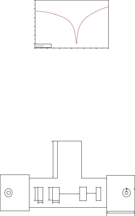
An example is given to show the transmission zero created by the shorted waveguide as shown in Figs. 4 and 5. Width and height of the short waveguide’s crosssection are 14 and 5 mm, length of the waveguide is set to 17.75 mm.
Fig. 4. A shorted waveguide shunted at the center of an evanescent-mode waveguide
402 L. He et al.
S parameters (dB)
-60
-70
-80
-90
-100
-110
S21
13.2 |
13.3 |
13.4 |
13.5 |
13.6 |
13.7 |
13.8 |
freqyency (GHz)
Fig. 5. Simulated results of Fig. 4
From Fig. 5, a transmission zero is created at a frequency of 13.54 GHz, half wavelength of this frequency is 18.1 mm, which is a little different from 17.75 mm. This small difference is caused by the influence between the two waveguides.
3 Result
After optimizing the filter by HFSS, parameters are determined and shown in Fig. 6, simulated results are shown in Fig. 7.
Figure 8 gives the magnetic field distribution at 13.58 GHz in the whole filter structure. From the figure it shows clearly that the signal at this frequency is almost all reflected to the input port.
|
17.75mm |
|
|
|
|
|
5.5mm |
6.1mm |
6.5mm |
14.5mm |
7.2mm |
|
|||
2.3mm |
3mm |
|
|
|
|
|
19.45mm |
Fig. 6. Key parameters of the simulated model

Evanescent-Mode Waveguide Filter with Transmission Zeroes |
403 |
S parameters (dB)
0 |
|
|
|
|
|
-20 |
|
|
|
|
|
-40 |
|
|
|
|
|
-60 |
|
|
|
|
|
-80 |
|
|
|
|
|
-100 |
S11 |
|
|
|
|
|
S21 |
|
|
|
|
11 |
12 |
13 |
14 |
15 |
16 |
frequency (GHz)
Fig. 7. Simulated results of the filter
Fig. 8. Magnetic field analysis of solution frequency at 13.58 GHz
The designed filter is then fabricated and measured. Figure 9 shows the manufactured filter. Figure 10 gives the simulated and measured results. The measured results accord well with the simulated ones. The measured transmission zero appears at 13.6 GHz, shifting a little from the simulated one, making upper stopband steeper. Due to fabrication error, the measured insertion loss is about 1 dB, not as good as the simulated. The losses of two SMA connectors also contribute to the measured insertion loss.
Fig. 9. Manufactured filter

404 L. He et al.
|
0 |
|
|
|
|
|
|
|
-15 |
|
|
|
|
|
|
(dB) |
-30 |
|
|
|
|
|
|
parameters |
-45 |
|
|
|
|
|
|
-60 |
|
|
|
|
|
|
|
S |
|
|
|
|
|
|
|
|
-75 |
S11 HFSS |
|
|
|
|
|
|
|
S21 HFSS |
|
|
|
|
|
|
|
S11 measured |
|
|
|
|
|
|
-90 |
S21 measured |
|
|
|
|
|
|
|
|
|
|
|
|
|
|
11.2 |
12.0 |
12.8 |
13.6 |
14.4 |
15.2 |
16.0 |
frequency (GHz)
Fig. 10. Simulated and measured results of the filter
4 Conclusion
A simple and direct method to generate a transmission zero in evanescent-mode waveguide filter by adding a shorted waveguide shunted in the coupling region between two resonators has been proposed in this letter. No cross coupling is needed, the whole filter could be simply designed by two steps: a traditional evanescent waveguide filter design and introducing of a shorted waveguide to produce a transmission zero. The measured results are in good accordance with the simulated ones, validating the proposed method presented in this letter.
References
1.Jaynes, E.T.: Ghost modes in imperfect waveguides. In: Proceedings of IRE, vol. 46,
pp.416–418, Feb 1958
2.Edson, W.A.: Microwave filters using ghost-mode resonance. In: Proceedings of IRE Electronic Components Conference, vol. 19, p. 2 (1961)
3.Bornemann, J., Arndt, F.: Rigorous design of evanescent-mode E-plane finned waveguide bandpass filter. In: Proceedings of IEEE MTT-S Digest, pp. 603–606 (1989)
4.Zhang, Q., Itoh, T.: Computer-aided design of evanescent-mode waveguide filter with nontouching E-plane fins. IEEE Trans. Microw. Theory Tech. MTT 36, 404–412 (1988)
5.Snyder, R.V., Bastioli, S.: Broad passband, wide stopband, high power evanescent mode filters using capacitively-loaded ridges. In: 42nd European Microwave Conference, 2012,
pp.176–179
6.Kun, L., Dexin, Q., Xingjian, Z., et al.: Analysis of stopband performance of evanescent mode waveguide bandpass filter loaded with tiny post. Appl. Electron. Tech. 43(8), 55–57, 65 (2017)
7.Caneron, R.J.: General coupling matrix synthesis methods for Chebyshev filtering functions.
IEEE Trans. MTT 47(4), 433–442 (1999)