

диафрагмированные волноводные фильтры / a984b06e-113d-49b8-8edb-2b1da5b0c177
.pdf1740 |
CMC, 2021, vol.68, no.2 |
Permittivity (F/m)
1500 |
|
|
|
|
1 |
|
|
|
|
|
|
|
Im |
|
|
|
|
|
|
|
|
Real |
0 |
|
|
R l |
1000 |
|
|
|
(H/m) |
|
|
|
Real |
|
|
|
|
Permeability |
-1 |
|
|
Im |
500 |
|
|
|
-2 |
|
|
|
|
|
|
|
|
|
|
|
||
|
|
|
|
|
-3 |
|
|
|
0 |
|
|
|
|
|
|
|
|
|
|
|
|
|
-4 |
|
|
|
-500 |
1 |
2 |
3 |
4 |
-5 1 |
2 |
3 |
4 |
|
|
|
Frequency (GHz) |
|
|
|
Frequency (GHz) |
|
|
|
|
(a) |
|
|
|
(b) |
|
Figure 10: Simulated results of slot-shaped unit. (a) Permittivity (δ), (b) permeability (μ)
Figure 11: Electromagnetic propagation when passing through a medium
A. TE polarization mode
Fig. 12a depicts the TE polarization mode. The metamaterial setup based on a slot is depicted along the y axis, so the electromagnetic waves propagate in the x direction. The electric fields of the rectangular microstrip antenna propagate along the y axis. Therefore, the TE polarization mode can have more magnetic fields of transmitted waves than reflected waves, as shown in Fig. 13a.
(a) |
(b) |
Figure 12: Geometries of resonator antenna. (a) TE, (b) TM
CMC, 2021, vol.68, no.2 |
1741 |
|
Rectangular patch |
|
|
|
Rectangular patch |
||
|
|
|
|
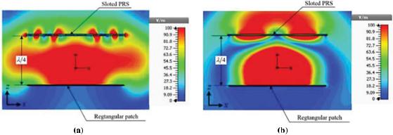
Figure 13: Electric field intensity propagation passing through the medium near-field distributions of proposed TE and TM modes. (a) TE mode, (b) TM mode
B. TM polarization mode
The metamaterial setup based on the slot-shaped structure is along the x axis, so the electromagnetic waves propagate in the y direction. Furthermore, the electric fields of a primary radiator propagate along the y axis. Consequently, the PRS polarization direction has only electric fields in the TM polarization mode, as displayed in Fig. 12b. In this case, the propagation of the transmitted waves can be less than that of the reflected waves, as shown in Fig. 13b.
From the theory explained above, the wave propagation is obstructed by the metamaterials based on the PRS slot-shaped structure along the x and y directions in the TE and TM polarization modes, respectively.
In TE mode, the slot-shaped metamaterials act as the rectangular microstrip superstrate installed on an antenna with a quarter-wavelength dimension in the medium for radiating in phase. Fig. 13a illustrates the near-field distribution of the proposed TE mode. It can be seen that the spread of waves radiating through a slot-shaped superstrate is small. The red area shows the maximum electric field strength from the rectangular patch antenna that could reach only marginally to the top of the metamaterial plate surface due to the impedance mismatch between the antenna and metal plate mounted along the cross-section. The yellow, green, blue, and dark blue areas show the decreasing electric field intensity.
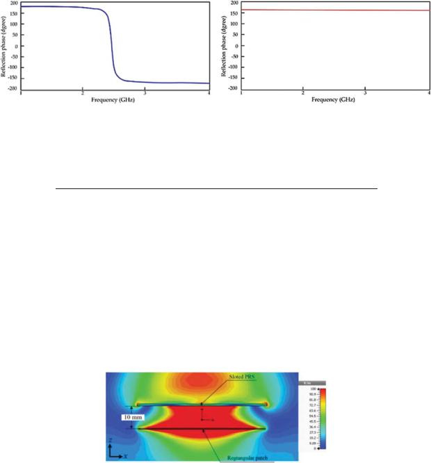
However, as shown in Fig. 13b, the wave propagation of the TM mode can be seen to be radiating very well. It was found that the maximum electric field strength could be exported from the antenna through the top of the metal sheet in the same direction due to the excellent impedance between the antenna and metal plate in the same horizontal direction. c, f , φPRS, and φEBG are the wave velocity, resonant frequency, reflection phase of the PRS, and reflection phase of the EBG, respectively. If the reflection phases of the EBG and PRS are 0◦ and 155◦ as plotted in Fig. 14, then the h parameter is 26.36 mm.
Simulation results of the proposed microstrip antenna gain with the EBG and metamaterial sheet are shown upon changing the distance between 0.04λ < h < 0.8λ starting from 5 mm up to 100 mm in increments of 10 mm, indicating that the gain was most affected in the response. From this result, it was found that the best distance was 10 mm, which had the highest gain of 11.97 dB, as shown in Tab. 1, since the distance between the antenna and metal sheet had an
1742 |
CMC, 2021, vol.68, no.2 |
offset angle of 0◦. The current density direction is shown in Fig. 15, simulation of the microstrip antenna with the full metal plate (EBG) in Fig. 16, and the best parameters in Tab. 2.
(a) (b)
Figure 14: Simulation results of reflection phases of metamaterials. (a) Reflection phase of EBG at 2.45 GHz, (b) reflection phase of PRS at 2.45 GHz
Table 1: Simulation gain results of proposed antenna
Distance between microstrip and metamaterial (mm) |
Gain (dB) |
5 |
11.70 |
10 |
11.97 |
20 |
10.83 |
30 |
9.88 |
40 |
9.72 |
50 |
9.79 |
60 |
10.36 |
70 |
10.34 |
80 |
10.31 |
90 |
10.29 |
100 |
10.28 |
|
|
Figure 15: Near-field distributions
CMC, 2021, vol.68, no.2 |
1743 |
|
(a) |
(b) |
|
|
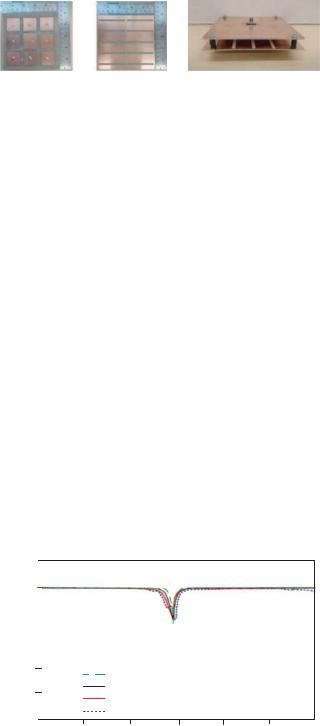
Figure 16: Photographs of proposed antenna. (a) |
Rectangular |
microstrip antenna with EBG |
||
surface and PRS (b) resonator antenna |
|
|
|
|
|
Table 2: Parameters of proposed antenna |
|||
|
|
|
|
|
|
Parameters |
|
Size (mm) |
|
|
|
|
|
|
|
W: Width of patch microstrip antenna |
37.54 |
|
|
|
Wg: Width of ground plane |
|
120.00 |
|
|
Ws: Width of patch EBG |
|
28.46 |
|
|
Wp: Separation width of slot PRS |
|
24.00 |
|
|
W1: Width of patch metamaterial |
|
15.30 |
|
|
L: Length of patch microstrip antenna |
28.93 |
|
|
|
Lg: Length of ground plane |
|
120.00 |
|
|
Ls: Length of patch EBG |
|
28.46 |
|
|
Lp: Length of slot PRS |
|
60.00 |
|
|
L1: Length of patch metamaterial |
|
61.22 |
|
|
L2: Length of slot metamaterial |
|
55.71 |
|
|
LEBG: Length of patch EBG |
|
35.00 |
|
|
g: Gap between a patch of EBG |
|
6.54 |
|
|
g1: Gap between a patch of metamaterial |
3.67 |
|
|
|
tant: Thickness of Cu antenna |
|
0.035 |
|
|
tground: Thickness of Cu ground |
|
0.035 |
|
|
hFR4: Thickness of FR4 |
|
1.60 |
|
|
h: Distance between radiating element and PRS |
10.00 |
|
|
|
|
|
|
|
S11 (dB)
10
0
-10
-20
-30 |
|
Simulation Antenna without EBG and Superstrate |
||||
|
|
|||||
-40 |
|
Simulation Antenna with EBG |
|
|
||
|
Simulation Antenna with EBG and Superstrate |
|
||||
|
|
|
||||
-50 |
|
Measurement |
|
|
|
|
|
|
|
|
|
|
|
1.0 |
1.5 |
2.0 |
2.5 |
3.0 |
3.5 |
4.0 |
Frequency
Figure 17: Simulated and measured S11 (dB)
1744 |
CMC, 2021, vol.68, no.2 |
The rectangular microstrip antenna prototype is surrounded by a mushroom-liked EBG, which was fabricated using two sides of FR4 sheet with a dielectric constant of 4.3, as shown in Fig. 16a. In addition, the PRS superstrate was located above the radiating element with a spacing of approximately 10 mm, as shown in Fig. 16b. When S11 is analyzed as shown in Fig. 17, Tab. 3 illustrates the simulated and measured results for the proposed antenna. The input impedances of simulation and measurement results were close to 50 .
Table 3: Simulated and measured results for antenna based on S11 and voltage standing wave ratio (VSWR)
Antenna |
S11 (dB) |
VSWR |
Zin ( ) |
|
Simulation antenna without EBG and superstrate |
−13.84 |
1.59:1 |
53.85 |
+ j12.05 |
Simulation antenna with EBG |
−12.31 |
1.63:1 |
69.24 |
+ j4.99 |
Simulation antenna with EBG and superstrate |
−12.65 |
1.62:1 |
49.85 |
− j20.93 |
Measurement of proposed antenna |
−10.05 |
1.92:1 |
47.94 |
− j25.34 |
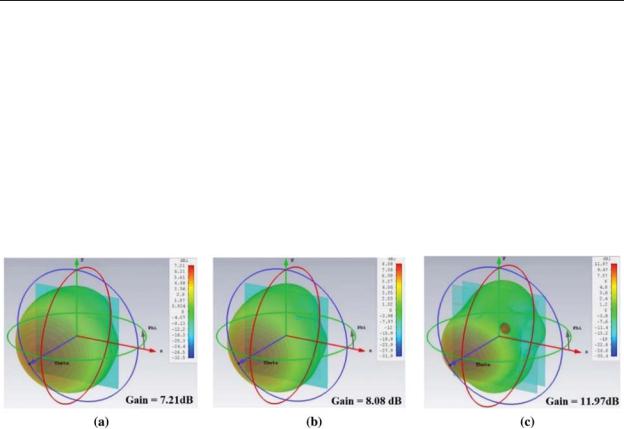
A microstrip antenna was reconstructed from a conventional patch using an EBG surface placed on a similar rectangular patch to improve directional gain from 7.21 to 8.08 dB. Subsequently, when the directional antenna was applied to the resonator antenna by adding the PRS superstrate, the maximum gain increased to 11.97 dB. When the proposed antenna was compared with the patch microstrip antenna, the directional gain efficiency was enhanced to 39.76%. The 3D perspective of the radiation pattern with maximum gain is shown in Fig. 18.
Figure 18: 3D perspectives of radiation pattern with maximum gain: (a) Patch microstrip antenna,
(b) patch microstrip antenna surrounded with EBG, and (c) proposed antenna
The results of comparing the measured and simulated gains of the microstrip antenna in Fig. 16 are shown in Tab. 4. These results tend to be in the same direction with the maximum gain of 11.97 dB. The efficiency was increased by 39.76%.
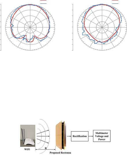
The radiation pattern in the E- and H-planes at a frequency of 2.45 GHz are plotted in Fig. 19. The characteristic of the radiated energy patterns is that of a directional radiation pattern. However, a back lobe perhaps appeared because the resonator antenna reflected and forwarded high-power waves. The half-power beamwidth in the E- and H-planes were 54.6◦ and 54.5◦, respectively.
CMC, 2021, vol.68, no.2 |
|
1745 |
||
Table 4: Comparison of measured and simulated gains of various antenna types |
||||
|
|
|
|
|
|
Antenna type |
Simulated gain (dB) |
Measured gain (dB) |
|
|
|
|
|
|
|
Microstrip antenna |
7.21 |
4.75 |
|
|
Microstrip antenna with EBG |
8.08 |
7.19 |
|
|
Proposed antenna |
11.97 |
11.62 |
|
|
|
|
|
|
|
|
z |
Measurememt |
|
|
z |
Measurememt |
|
|
0 |
|
|
0 |
||
0 |
|
Simulation |
0 |
|
Simulation |
||
330 |
|
330 |
|
||||
|
|
30 |
|
|
30 |
||
|
|
|
|
|
|
||
-10 |
|
|
|
-10 |
|
|
|
-20 |
300 |
|
60 |
-20 |
300 |
|
60 |
|
|
|
|
|
|
||
-30 |
|
|
|
-30 |
|
|
|
-40 |
270 |
|
90 x |
-40 |
270 |
|
90 y |
-30 |
|
|
|
-30 |
|
|
|
-20 |
240 |
|
120 |
-20 |
240 |
|
120 |
|
|
|
|
||||
-10 |
|
|
|
-10 |
|
|
|
0 |
210 |
|
150 |
0 |
210 |
|
150 |
|
|
180 |
|
|
|
180 |
|
|
|
(a) |
|
|
|
(b) |
|
Figure 19: Simulated and measured radiation patterns. (a) E-plane, (b) H-plane
3.2 Rectifier
The DC energy-harvesting measurement from connecting the prototype antenna with the rectifier and voltage multiplier circuits is shown as a block diagram in Fig. 20. The experiment was done with voltage multiplier circuits of 6, 8, 10, and 12 times, tested at 0.6 m, which was the best distance for receiving maximum voltage. It was found from the experimental results that a multiplier circuit of 8 times yielded better performance than that of 6, 10, or 12 times, as shown in Tab. 5.
Figure 20: Block diagram of ambient RF energy harvesting

1746 |
|
|
|
|
|
CMC, 2021, vol.68, no.2 |
|||
|
Table 5: Energy-harvesting measurement results |
|
|
|
|||||
|
|
|
|
|
|
|
|||
|
Distance (m) |
Measurement results |
Voltage multiplier circuits |
||||||
|
|
|
|
|
|
|
|
|
|
|
|
|
6 |
8 |
10 |
12 |
|
|
|
|
|
|
|
|
|
|
|
||
0.6 |
Voltage (mV) |
2.23 |
2.71 |
2.63 |
2.59 |
|
|||
|
|
|
|
|
|
|
|
|
|
4 Rectenna System Measurement Results
Experiments were carried out on two parameters for receiving maximum energy: signal receiving distance and direction angle of the Wi-Fi spot and rectenna response. The signal receiving distances were 0.5, 1, 1.5, 2, 2.5, and 3 m, and the direction angles of the Wi-Fi spit and rectenna response were 0◦, 15◦, 30◦, 45◦, 60◦, 75◦, and 90◦. The best value was at a distance of 1 m and the direction of 45◦. The results were a voltage of 2.82 mV, current of 0.34 mA, and power of 0.95 μW, as shown in Tab. 6. In more than 3 meters measuring distances and the direction angle greater than 90◦, the measurement was lower than 0.05 mV/mA, causing the signal meter not to display on the screen. Wi-Fi transmitter was the TP-Link TL-WRB840N, commonly used in Thailand, connected to the directional antenna with the transmitting power of −30.04 dB.
Table 6: Energy harvesting measurement results
Angle |
Measurement results |
Distance (m) |
|
|
|
|
||
|
|
|
0.5 |
1 |
1.5 |
2 |
2.5 |
3 |
|
|
|
|
|
|
|
|
|
0◦ |
Voltage (mV) |
1.64 |
1.85 |
1.72 |
1.56 |
1.12 |
0.09 |
|
|
Current (mA) |
0.19 |
0.21 |
0.19 |
0.17 |
0.10 |
0.08 |
|
15◦ |
Power (μW) |
0.31 |
0.39 |
0.32 |
0.26 |
0.11 |
0.007 |
|
Voltage (mV) |
1.78 |
1.98 |
1.74 |
1.62 |
1.24 |
1.17 |
||
|
Current (mA) |
0.20 |
0.23 |
0.21 |
0.15 |
0.09 |
0.07 |
|
30◦ |
Power (μW) |
0.35 |
0.45 |
0.36 |
0.24 |
0.11 |
0.08 |
|
Voltage (mV) |
2.53 |
2.80 |
2.28 |
1.82 |
1.34 |
1.12 |
||
|
Current (mA) |
0.21 |
0.32 |
0.21 |
0.12 |
0.09 |
0.08 |
|
45◦ |
Power (μW) |
0.53 |
0.89 |
0.47 |
0.21 |
0.12 |
0.08 |
|
Voltage (mV) |
2.54 |
2.82 |
2.31 |
1.97 |
1.46 |
1.25 |
||
|
Current (mA) |
0.21 |
0.34 |
0.24 |
0.13 |
0.09 |
0.08 |
|
60◦ |
Power (μW) |
0.53 |
0.95 |
0.55 |
0.25 |
0.13 |
0.10 |
|
Voltage (mV) |
2.14 |
2.52 |
2.23 |
1.75 |
1.27 |
1.16 |
||
|
Current (mA) |
0.20 |
0.24 |
0.22 |
0.18 |
0.10 |
0.08 |
|
75◦ |
Power (μW) |
0.42 |
0.60 |
0.49 |
0.31 |
0.12 |
0.09 |
|
Voltage (mV) |
2.14 |
2.52 |
2.23 |
1.75 |
1.27 |
1.16 |
||
|
Current (mA) |
0.19 |
0.23 |
0.19 |
0.10 |
0.09 |
0.07 |
|
90◦ |
Power (μW) |
0.40 |
0.57 |
0.42 |
0.17 |
0.11 |
0.08 |
|
Voltage (mV) |
2.01 |
2.12 |
1.92 |
1.68 |
1.08 |
1.04 |
||
|
Current (mA) |
0.13 |
0.18 |
0.14 |
0.09 |
0.07 |
0.05 |
|
|
Power (μW) |
0.26 |
0.38 |
0.26 |
0.15 |
0.07 |
0.05 |
|
|
|
|
|
|
|
|
|
|
CMC, 2021, vol.68, no.2 |
1747 |
5 Discussion
The design and construction of a rectenna system using a directional microstrip antenna with an integrated magnetic stripe design (EBG) plate with a multiple voltage circuit were presented. The antenna designed in the present work was compared with those designed in previous works as follows.
In [29], an uncomplicated antenna with a gain of 8.6 dBi for low-energy harvesting at the 2.45 GHz frequency band was designed. The rectenna in [30] consisted of an antenna with a directional gain of 6.7 dB at 2.45 GHz. A rectifier circuit with a HSMS2850 diode achieved low-energy harvesting with an efficiency of 63% when the input power was 0 dBm. The designed antenna matched the rectifying circuit and eliminated unwanted harmonics, resulting in an 83% efficiency when using a 1400resistor and converting power up to 83% at −15 dBm. This antenna design is not complicated, but has low gain and high power consumption.
A rectifier circuit with four switch diodes and an interdigital capacitor was designed to increase the DC output voltage in another antenna [31] that operated at the 2.45-GHz frequency band to reduce high harmonic values and had a gain of 7.13 dB, resulting in an efficiency of 78.7% when using 4 k impedance with a transmitted signal power of 20 dBm. This antenna is also not complicated, but has low gain and high transmitting power.
Another antenna was designed using square-shaped tuning techniques to tune the impedance bandwidth and increase the maximum gain to 5.6 dB [32]. This antenna is compact, measuring 18 mm × 30 mm, with an L-shaped impedance-matching network rectifier to allow the input impedance to match that of the antenna. A maximum voltage of 3.24 V was obtained with a load resistance of 5 k . Its maximum efficiency was 75.5% in simulation and 68% as measured with a transmitted power of 5 dBm at 2.45 GHz. This antenna is small and compact, but has low gain and high transmitting power.
In [33], frequency-selective-surface (FSS) sheet structure techniques were used for RF energy harvesting with a geometric shape consisting of a sequence of unit cells. The gain was 9.4 dB when connected with a full-wave rectifier circuit that could convert power up to a conversion rate of 61% at a transmitted power of 15 dBm. The gain and transmitted power are both high, but the structure is complicated.
In [34], a square 2 × 2 array antenna designed by adding an I-shaped tuning stub, resulting in a gain of 13.4 dB, was studied. The rectifier used a serial mounting diode and a microstrip sheet as a capacitor, which was essentially a DC bandpass filter, resulting in a high RF-to-DC conversion efficiency of the modified circuit of 80%. In practical operation, a maximum voltage of 18.5 V was achieved, along with a power conversion rate of up to 77.2% at 21 dBm of signal power when using 3.5-k resistance. The gain is high, but the antenna structure is too large, i.e., 200 mm × 200 mm.
The authors of [35] introduced a monopolar antenna using triangular grooving techniques on the ground plane and an I-shaped reflector in implementing the air-gap technique. A gain of 8.36 dB was obtained. Combined with a full-wave rectifier circuit, this antenna could convert power at a conversion rate of up to 40% at 0 dBm at a maximum voltage of 0.46 V and convert voltage up to 6 V when using signal power up to 30 dBm. The antenna structure is not complicated, but has low gain.

1748 |
CMC, 2021, vol.68, no.2 |
In the method proposed in the present paper, a low signal power on the input power of −30.04 dB was used, transmitted at a distance of 1 m with a higher efficiency of 95.88%, as shown in Tab. 7.
Table 7: Comparison of rectenna efficiencies
Reference |
Frequency |
Substrate |
Antenna size (mm3) |
R (m) |
Input |
Gain |
Efficiency |
|||
|
(GHz) |
|
|
|
|
|
|
power |
(dB) |
(%) |
|
|
|
|
|
|
|
|
(dBm) |
|
|
|
|
|
|
|
|
|
|
|
||
[29] |
2.45 |
RT/Duroid |
87 |
× 80 × 1.52 |
|
−15 |
8.60 |
83 |
||
[30] |
2.45 |
NPC-F260 |
110 |
× 110 × 2.60 |
|
0 |
6.70 |
63 |
||
[31] |
2.45 |
FR4 |
85 |
× 100 × 1.60 |
|
20 |
7.13 |
78.70 |
||
[32] |
2.37–2.52 |
FR4 |
18 |
× 30 × 1.60 |
1 |
5 |
5.60 |
68 |
||
[33] |
2.45 |
Rogers |
228.60 × 304.80 × 1.524 |
1 |
15 |
9.40 |
61 |
|||
[34] |
2.45 |
FR4 |
200 |
× 200 |
× 3 |
|
21 |
13.40 |
77.20 |
|
[35] |
2.45 |
FR4 |
100 |
× 100 |
× 1.60 |
1 |
0 |
8.36 |
40 |
|
Present work |
2.45 |
FR4 |
120 |
× 120 |
× 1.60 |
1 |
−30.04 |
11.62 |
95.88 |
|
6 Conclusions
The method for designing the structure and energy-harvesting circuit for an antenna proposed this research increased the antenna gain, reduced the complexity of the antenna structure, and obtained efficiency with a multiple voltage circuit. The antenna structure is a rectangular directional microstrip that is combined with an EBG mushroom-shaped magnetic frequency gap that can control the radiation direction and a 2 × 5 I-shaped metamaterial, placed at a distance of 10 mm. The gain increased from 7.21 to 11.67 dB with an efficiency of 39.76%. The entire antenna structure was constructed on a FR4 PCB with a constant electrical conductivity of 4.3 at 2.45 GHz in a Wi-Fi system. The energy was harvested with a rectifier circuit to convert the AC signal to DC and combined with an 8-times-multiplier voltage circuit that yielded voltages greater than those yielded by 6-, 10-, and 12-times-multiplier voltage circuits and increased the efficiency of the circuit by doubling the DC voltage 8 times. The optimum received energy was at an angle of 45◦ and a distance of 1 m. The obtained voltage was 2.82 mV, the current 0.34 mA, and the power 0.95 μW, with an efficiency of 95.88%. The proposed method is more efficient, the structure is not complicated, and less adjustment is needed.
Acknowledgement: The authors thank the Department of Telecommunications Engineering, Fac-
ulty |
of |
Engineering and Architecture, Rajamangala University of Technology Isan, Thailand, |
||||||||
for |
equipment support and |
research |
funding. Moreover, |
they gratefully |
acknowledge |
the |
||||
use |
of |
computer simulation |
software |
for supporting |
this |
research |
work |
sponsored |
by |
the |
School |
of Telecommunication Engineering, Suranaree |
University |
of Technology, |
Nakhon |
||||||
Ratchasima, Thailand.
Funding Statement: This work is supported by the Rajamangala University of Technology Thanyaburi research and development fund.
Conflicts of Interest: The authors declare that they have no conflicts of interest to report regarding the present study.
CMC, 2021, vol.68, no.2 |
1749 |
References
[1]M. H. Nehrir, C. Wang, K. Strunz, H. Aki, R. Ramakumar et al., “A review of hybrid renewable/alternative energy systems for electric power generation: Configurations, control, and applications,”
IEEE Transactions on Sustainable Energy, vol. 2, no. 4, pp. 392–403, 2011.
[2]T. H. Oh, S. Y. Pang and S. C. Chua, “Energy policy and alternative energy in Malaysia: Issues and challenges for sustainable growth,” Renewable and Sustainable Energy Reviews, vol. 14, no. 4, pp. 1241– 1252, 2010.
[3]P. McKendry, “Energy production from biomass (part 1): Overview of biomass,” Bioresource Technology, vol. 83, no. 1, pp. 37–46, 2002.
[4]M. S. Dresselhaus and I. L. Thomas, “Alternative energy technologies,” Nature, vol. 414, no. 6861, pp. 332–337, 2001.
[5]V. Devabhaktuni, M. Alam, S. S. S. R. Depuru, R. C. Green II, D. Nims et al., “Solar energy: Trends and enabling technologies,” Renewable and Sustainable Energy Reviews, vol. 19, no. 8, pp. 555–564, 2013.
[6]X. Lu, P. Wang, D. Niyato, D. I. Kim and Z. Han, “Wireless networks with RF energy harvesting: A contemporary survey,” IEEE Communications Surveys & Tutorials, vol. 17, no. 2, pp. 757–789, 2014.
[7]M. Piñuela, P. D. Mitcheson and S. Lucyszyn, “Ambient RF energy harvesting in urban and semiurban environments,” IEEE Transactions on Microwave Theory and Techniques, vol. 61, no. 7, pp. 2715– 2726, 2013.
[8]F. Iwanda, Z. Zulfi and Y. Wahyu, “Rectifying antenna (rectenna) untuk sinyal tv uhf 470–806 Mhz,” eProceedings of Engineering, vol. 5, no. 3, pp. 5483–5490, 2018.
[9]R. K. Sidhu, J. S. Ubhi and A. Aggarwal, “A survey study of different RF energy sources for RF energy harvesting,” in Int. Conf. on Automation, Computational and Technology Management, Amity University, London, United Kingdom, pp. 530–533, 2019.
[10]M. Hasan, M. Rahman, M. R. I. Faruque, M. T. Islam and M. U. Khandaker, “Electrically compact SRR-loaded metamaterial inspired quad band antenna for bluetooth/WiFi/WLAN/WiMAX system,” Electronics, vol. 8, no. 7, pp. 790, 2019.
[11]C. A. Balanis, “Antenna theory and design,” NY, USA: John Willey & Sons, 1997.
[12]W. Naktong, P. Boonmaitree, S. Kornsing, E. Khoomwong and A. Ruengwaree, “CPW-fed rectangular aperture antenna with two-step ground-plane tuning for UWB applications,” RMUTI Journal Science and Technology, vol. 7, no. 2, pp. 50–66, 2014.
[13]W. Naktong, N. Fhafhiem, A. Innok and A. Ruengwaree, “Study of rectanna using directive antenna at frequency of 2.45 GHz,” in 10th South East Asian Technical University Consortium Symp., Tokyo, Japan, 2016.
[14]E. K. I. Hamad and A. Abdelaziz, “Metamaterial superstrate microstrip patch antenna for 5G wireless communication based on the theory of characteristic modes,” Journal of Electrical Engineering, vol. 70, no. 3, pp. 187–197, 2019.
[15]A. Lalbakhsh, M. U. Afzal, K. P. Esselle, S. L. Smith and B. A. Zeb, “Single-dielectric wideband partially reflecting surface with variable reflection components for realization of a compact high-gain resonant cavity antenna,” IEEE Transactions on Antennas and Propagation, vol. 67, no. 3, pp. 1916– 1921, 2019.
[16]B. A. Munk, “Frequency selective surfaces: Theory and design,” NY, USA: John Wiley & Sons, 2005.
[17]S. Luo, Y. Li, Y. Xia and L. Zhang, “A low mutual coupling antenna array with gain enhancement using metamaterial loading and neutralization line structure,” Applied Computational Electromagnetics Society Journal, vol. 34, no. 3, pp. 411–419, 2019.
[18]H. Ö. Yılmaz and F. Yaman, “Meta-material antenna designs for a 5.8 GHz doppler radar,” IEEE Transactions on Instrumentation and Measurement, vol. 69, no. 4, pp. 1775–1782, 2019.
[19]M. E. Atrash, M. A. Abdalla and H. M. Elhennawy, “A wearable dual-band low profile high gain low SAR antenna AMC-backed for WBAN applications,” IEEE Transactions on Antennas and Propagation, vol. 67, no. 10, pp. 6378–6388, 2019.