

Ebooki / cb-amplifier_8wse
.pdfAn Easily Constructed
High-Quality Single-Ended 8W Amplifier
Using Standard Valves and the
Lundahl LL 1664 Output Transformer
Claus Byrith
2002
31-10-02 |
1 |

Preface
After the publication a year ago of my paper Power Amplifiers with Valves I have received a lot of comments and very much to my surprise I learned that a great deal of interest in single-ended (SE) amplifiers exists, and I have been asked for a similar paper concerning such amplifiers.
I admit that I have been very reluctant. I still remember when I was 17 and my financial situation finally permitted me to buy a decent transformer for 2 EL84s in push-pull (PP) capable of handling 10 Watts, and I remember the joy that came from listening to my first PP amplifier. I never thought that I was ever again to show any interest in SE amplifiers.
The output transformer is by far the most critical component in any valve amplifier. The problems to be solved by the manufacturer of output transformers are even more complex for an SE-transformer than for a PP-transformer. I shall return to this matter later, but I can without exaggerating say that the output transformer found in the SE-amplifiers of almost every radio receiver, tape recorder or record player in the late fifties and in the sixties was very poor as was the design of the amplifiers. The advent of stereo in these years did not improve this situation. On the contrary it worsened because the public would only accept a small rise in the investment costs when upgrading to stereo. Both amplifiers and speaker systems became simpler. Warning voices claimed that each of the two channels in stereo should be at least as good as your mono channel if full advantage of the new technique was to be taken. For many years these warnings were neglected, and the equipment I remember from the pioneering years of stereo made me loathe just the naked principle of the SE-amplifier.
Today I am perhaps more open-minded, and when Mr. Per Lundahl from Lundahl Transformers told me about his SE-transformers I became curious and decided to investigate the matter and in your hands you are holding the results of my efforts.
2. The Principle
2
As can be seen, the design of the SE-amplifier is simple. A combined input stage and driver drives the output valve, and a transformer matches the valve and the speaker system. A PPamplifier must have a phase-splitter to provide signals of equal magnitude but opposite phase for the two output valves. The phase-splitter is a very critical part of the PP-amplifier, and its behaviour is of great importance for the performance of the amplifier. The design of this stage takes skill and care as explained in my earlier paper.
The SE supporters claim that simplicity and a very short signal path is the key to the survival of and even renewed interest in their favourite type of amplifier. The short signal path is however not a virtue per se. If you want to move from point A to point B the shortest path is of course a straight line, but if following this line makes you traverse a dunghill you will surely arrive at point B in a poor condition whereas a small detour around the obstacle would enable you to reach point B in a perfectly clean condition. Exactly the same applies to the signal travelling from input to output of an amplifier. If the short path should be the best, we have to take great care when paving it with the smoothest stones available and place them very carefully so that the surface of the path becomes impeccably flat.
3. The Transformer
As stated in the preface, the transformer is very important, and we shall in this chapter look into the properties and problems of the output transformper.
Basically a transformer consists of a core of a material that can be magnetized wound with two coils. The ratio between the numbers of turns in the two coils determines the transformation ratio of the transformer. The energy is transferred to an alternating magnetic field and back to electric power again.
If an output valve can deliver 10 Watts into a load of 3000 Ω, and the speaker system is 8 Ω, we use transformer to match the load from the formula
P = |
e2 |
where P is the power in Watts |
|
r |
|||
|
|
||
|
|
e is the voltage across the load |
|
|
|
r is the resistance of the load |
31-10-02 |
3 |
We can determine the signal voltage that is found on the primary of the transformer
10 = |
e2 |
or e2 = 30000 or e = 30000 = 173.2 V |
|
||
3000 |
|
|
We want the 10 Watts delivered in 8 Ω so the formula for the secondary is
10 = |
e2 |
or e2 = 80 or e = 80 = 8.95 V |
|
||
8 |
|
|
The turns ratio of the transformer must be 173.2 V = 19.35 : 1 8.95 V
Which is the same as the square root of the primary impedance divided by the secondary imped-
ance, |
3000 = 375 ≈ 19.35 |
|
8 |
In the extreme case where the secondary is unloaded or an open circuit, the primary should act as no load for the AC signal too, the impedance should be infinite. This will be the case if the induction of the primary coil is infinite. This will of course never be completely possible. The impedance of the coil is also frequency dependent, meaning that if induction is not infinite the impedance will decrease with decreasing frequency. The lower the frequency that a transformer must be capable of handling the higher the induction must be if losses and distortion are to be kept within reasonable limits.
Let us suppose another extreme: Short circuit of the secondary. If the transformer is ideal the primary should act as a short circuit too, meaning that DC resistance and AC impedance should be zero too. This will clearly never be the case. The DC resistance of the both primary and secondary remains, and because the turns of the primary and the secondary are not infinitely close coupled, a little inductance and therefore a little AC impedance of the primary will also remain. The remaining inductance is called the primary leakage inductance, and this inductance is harmful because it acts as an inductance in series with the load, in this case the speaker, compromis-
ing HF response.
Even a small leakage induction can be of serious consequences. 8mH leakage is a fine value for a single end output transformer 3KΩ/8Ω and it does not sound of much. But the impedance is
Z = 2π · f · Le where |
f is the frequency in Hz |
|
Le is the leakage induction in Hy |
at e.g. 50KHz: |
Z = 2 . 3.14 . 50.000 . 0.008 = 1570Ω |
which of course is not unimportant compared to the pnominal 3000Ω primary impedance!
4

Another factor is the capacitance across the primary. This acts as an unuseful load in parallel with the primary, and since this load is increasing with frequency this capacitance is also deteriorating HF performance. It shows how important a low output resistance from the valve is because the lower the output resistance the less the additional frequency dependent load means.
The transformers of the fifties were wound on EI cores as shown:
secondary
the “I”
primary
the “E”
The ”E” seen from above
 insulating foil
The core is laminated to avoid eddy currents
The secondary was normally wound outside the primary, so coupling between the innermost turns of the primary and the secondary was not close, resulting in considerably leakage induction.
In the PP transformer the supply voltage for the two valves is applied to the centre of the primary. The anode currents are floating in opposite directions in the two halves of the primary. If the currents are equal their resulting static magnetization of the core will be zero. In the SE transformer the anode current of the single valve generates a static magnetic field that magnetizes the core permanently and causes serious problems. If the core saturates, the primary inductance drops almost to zero, and severe distortion occurs. If measures are not taken, saturation takes place when even a very moderate DC current flows. The core must cope not only with the static magnetic field but also at the same time be able to handle the alternating field generated by the signal current.
There are four ways to deal with this problem.
1.The number of turns in both primary and secondary can be lowered. The magnetic field is proportional to the number of turns multiplied by the current, so lowering the number of turns reduces the magnetic field.
Unfortunately the inductance is lowered too, causing bass problems in the amplifier.
2.The core can be made larger. There will be more iron to magnetize, so the resulting magnetization for a given current will be lower.
31-10-02 |
5 |
Unfortunately this increases the diameter of each turn, which again increases DC resistance and capacitance between turns and between layers of turns, causing problems at both ends of the audio band. The price will of course go up too.
3.An air gap can be made in the core. Since the magnetic field travels thousands of times easier in the core than in the air, an air gap is a very efficient obstacle for the magnetic field.
Unfortunately an air gap reduces primary inductance and decreases coupling between primary and secondary, so also the air gap is a hazard to the performance in both ends of the audio band.
Note that the reduction of the inductance is very substantial, often by a factor 5 to 10, so when an air gap for say 80mA is introduced primary induction may very well go down by 75%.
4.The transformer could be equipped with an additional winding for a DC current generating a magnetic field of the same magnitude as the field generated by the primary but in the opposite direction. This field would cancel the magnetization caused by the quiescent current in the output valve.
This is in theory an elegant solution, but unfortunately the extra winding requires space without being involved in the transformation process, and some regulating circuit to control that the counter-current is correct will be needed. The whole idea of simplicity will then be gone. I have to say that this solution has often crossed my mind. I have, however, never seen or heard about a transformer with a winding designed for this particular pur-
pose.
All factors are conflicting here and the manufacturer is put in a position like Ulysses on his way home from Troy: When he wants to pass Scylla in safe distance he gets so close to Charybdis that he is in great danger to be swallowed up. All factors are conflicting and only a very careful design and a superb core material can produce an acceptable transformer.
I was triggered by this information from Mr. Per Lundahl: He told me that he makes transformers with air gaps customised for the current you want to pass through the output valve. The air gaps are dimensioned so that the quiescent current generates a magnetic flux of 0.9 Tesla in the core. This is in the middle of the linear part of the magnetization curve for the core material, meaning that a variation of +/÷ 0.6 Tesla can be handled fairly linearily.
This also tells us that choosing a transformer for say 100mA when only 80 mA is needed “just to be on the safe side” is wrong. First you lose primary inductance and second, the transformer is not operating from the mid-point of the linear part of the curve.
6
The laminated cores are cut and the ends are precision machined and polished so that the air gaps are completely uniform over their total area. The benefit is a primary inductance which is very little dependent on signal current. This is clearly and positively reflected in performance in the LF end of the spectrum. In the SE transformers of my youth the air gap was formed by a piece of cardboard between the “E” and the “I”, and my impression is that the philosophy of the design was: rather too thick than too thin because the distortion caused by a saturating transformer is very nasty. The often generously dimensioned air gap meant a leaky and lossy transformer with low primary inductance and consequently poor performance at both ends of the audio spectrum.
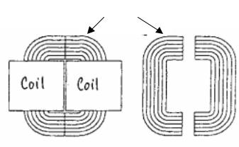
In the light of this the initiative of Lundahl is very interesting, and I ordered and LL1664 3kΩ/8Ω SE output transformer with an air gap for 80mA. The transformer is rated for 8W at 30 Hz. It has the same size and shape as the 35W PP transformer I used in my PP amplifier last year. Lundahl uses method 2 and 3 in order to cope with the static field but not option 1, which I find is a praise-worthy method. Furthermore the Lundahl Transformers are wound on C-cores as
shown:
Laminated core
Each coil has four sections
1.Part of secondary
2.Part of primary
3.Part of secondary
4.Part of primary
The two coils are identical so the transformer is ifn total divided into 8 sections giving a very close coupling between primary and secondary
This means that the grain orientation in the core can be perfect everywhere in the core and that a greater part of the core can be covered with coils. The secondary is wound in sections between layers of primary, and the turns are very neatly placed so that the space available is used entirely. No air due to a messy winding technique is found. These precautions reduce leakage induction considerably, and optimising the air gap for the actual current means that the decrease of primary inductance is at least not bigger than absolutely necessary. The actual primary inductance is 22H and the leakage is only 8 mH, an excellent achievement.
31-10-02 |
7 |
This short introduction will not make you an expert on transformers and there are of course many other aspects of great importance like e.g. phase shift. I just wanted to familiarize you with a few of the main obstacles the manufacturer must deal with when he wants to make a good output transformer.
4. Design Goals
Before embarking on a project like this it is wise to state exactly what to achieve and by which means.
I want to build an SE amplifier capable of producing 8W, because this is what my transformer is intended for.
I shall try to use widely available standard valves in order to keep costs reasonable, but I am prepared to make a series of investigations to make it possible for me to choose the most suitable solution to the very important question: the configuration of the output stage. Valve tables are not very helpful here. Their application suggestions are always limited to the standard pentode coupling with emphasis on maximum power.
I shall try to make the circuit simple and understandable, and I want to make it possible to use the amount of negative feedback that suits the user best, ranging from 0 to 10dB, and I shall limit myself to two valves.
Since no mains ripple cancellation takes place in the transformer as it does in PP amplifiers, I am prepared to use a filter choke in the power supply.
These considerations lead me to choose EL34 as my output valve. I want it to behave as closely as possible to a triode without sacrificing more than 25% of the power that the valve can provide in a normal coupling.
I tried the five circuits shown on the next page with two different supply voltages, 275 and 375 Volts. The circuits with a tap on the primary for the screen grid were tested with taps at different points.
The first thing that I found was that maximum power provided by the triode configuration was so low that this circuit was left out of any further consideration for me.
The next thing was that with 275V supply, tapping at a lower point than 16% would also limit power unacceptably, whereas even tapping at 50% did not affect power significantly when supply voltage was 375.
I measured input voltage requirements, total harmonic distortion at 1000Hz and output resistance for the circuits 2 to 5, and the results are given in two tables on the page after the circuits.
8

31-10-02 |
9 |

A very interesting point is the output resistance1, not only because a low output resistance provides electromagnetic damping of resonances in the speaker but also because speakers are designed to have the flattest frequency response when fed with a frequency independent voltage. Since impedance of speakers varies considerably with frequency, an amplifier with a high output resistance will produce higher drive voltages at points where the impedance curve peaks, and this is where the speaker has resonances. A high output resistance tends to aggravate resonances and should consequently be avoided. I prefer an output resistance less than 1/10 of the nominal speaker impedance giving a damping factor of 10, but I learned that for many people the damping factor seems to be less important, and what is called “a more rounded, warmer bass” is achieved. It seems that a damping factor of 2 to 5 is enough. Even though I do not a priori agree, I am prepared to give my experiments the benefit of the doubt.
As expected the output resistance drops when the screen grid is connected to a tap on the primary. We know that from PP amplifiers where this way of connecting the screen grids is referred to as “ultra linear” or “distributed load”.
It was also expected that output resistance would go down when the secondary of the transformer was used as a cathode feedback coil too. Normally when this method is used, a separate coil with about 10% of primary turns is used. The famous QUADII uses such a transformer. I have however never found a commercially available SE transformer with a cathode coil, but since I wanted to study the effect of transformer coupled cathode feedback, I tried to use the sec-
ondary both as such and at the same time as a cathode primary. The ratio 3000 ≈ 19 is only a
8
little more than half the normal but nevertheless the effect is striking. With a 375V supply and tap at 50% for the screen grid the inclusion of cathode feedback halves output resistance.
The output resistance tells us about the anode resistance in the valve, which in turn tells us about the steepness of the curves representing anode voltage versus anode current. The lower the anode resistance the steeper the curves, the more triode-like they are and the lower the output resistance will be.
From the tables it can also be seen that when cathode feedback and distributed load create what I call an “artificial triode”, the necessary drive voltage is increased and distortion is reduced precisely as if the EL34 was a real triode. The distortion is mainly second harmonic, again very similar to the distortion generated by a real triode.
The generation of second harmonic distortion in a triode is due to the fact that the relationship between grid voltage and anode current becomes less linear at low anode currents, meaning
1 The term output resistance is used throughout in this paper, since it is the normal term used in audio circles. The term “internal impedance of the stage” would be more correct.
10