

ppl_05_e2
.pdfID: 3658
Customer: Oleg Ostapenko E-mail: ostapenko2002@yahoo.com Customer: Oleg Ostapenko E-mail: ostapenko2002@yahoo.com
CHAPTER 5: DRAG
Interference Drag.
Although the form drag of any aircraft component may be minimised by streamlining, it is not always the case that two streamlined components will generate minimum form drag, if those components are joined together. It can be demonstrated by experiment that the form drag generated by a complete aircraft is greater than the sum of the separate elements of form drag generated by each individual component.
This additional increment in form drag is called interference drag. Interference drag is caused, primarily, by the joining of the wings to the fuselage.
Figure 5.10 Interference drag occurs primarily at the junction between wing and fuselage, and may be reduced by fitting fairings or fillets.
Interference drag can be reduced at the junctions where components meet by ensuring that no sharp angles are formed by the junctions. This is achieved by ftting fairings or fllets (see Figure 5.10).
Interference
drag is caused, primarily, by
the junctions of wing and fuselage.
Parasite drag varies directly with the square of the indicated airspeed.
The Variation of Parasite Drag with Aircraft Speed.
Figure 5.11 Parasite drag increases as the square of the indicated airspeed.
Analysis of the total drag acting on an aircraft is complex. However, it is fairly accurate to say that parasite drag increases as the square of the indicated airspeed.
So if, at 90 knots, the parasite drag acting on an aircraft is 200 pounds (lbs) force, (91 kilograms force or 892 Newtons), the parasite drag at 180 knots would be four times that value: 800 lbs force, (324 kilograms force or 3 568 Newtons). Figure 5.11 illustrates graphically how parasite drag increases with indicated airspeed. The graph is a curve, because, as we have learnt, the increase in parasite drag varies as the square of the indicated airspeed.
97
Order: 6026
Customer: Oleg Ostapenko E-mail: ostapenko2002@yahoo.com
Customer: Oleg Ostapenko E-mail: ostapenko2002@yahoo.com
CHAPTER 5: DRAG
INDUCED (OR LIFT-DEPENDENT) DRAG.
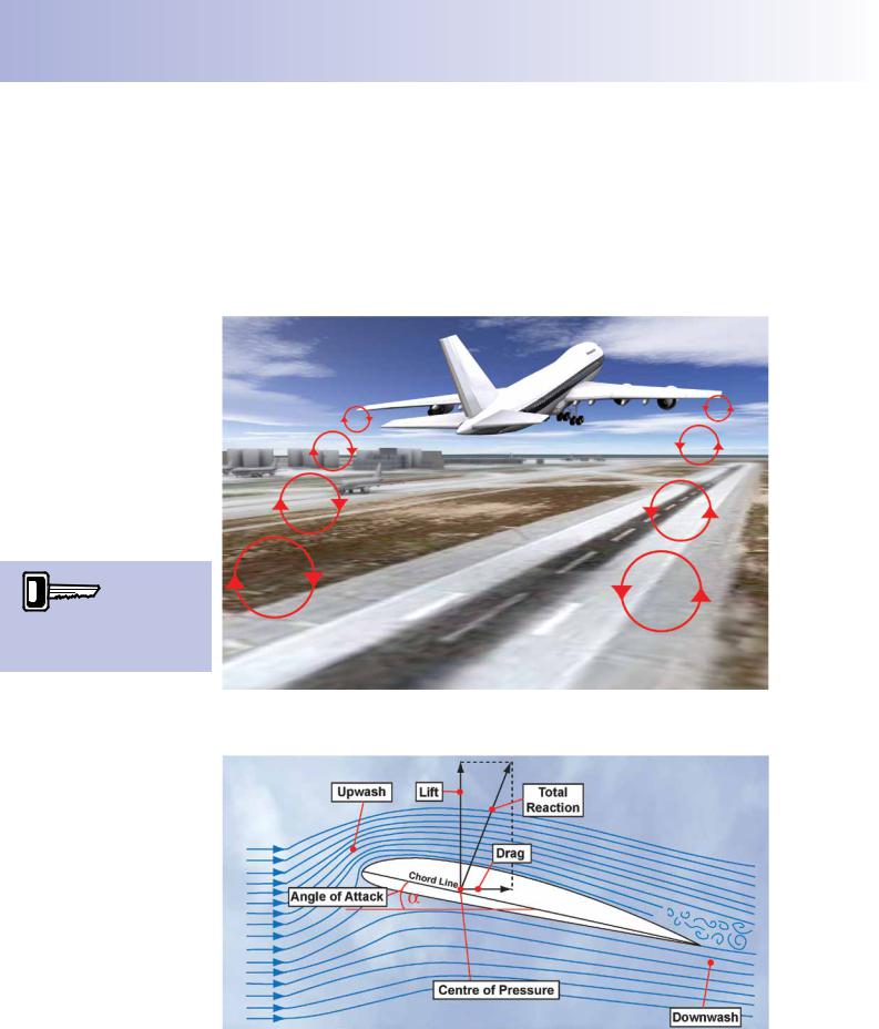
All parts of an aircraft generate parasite drag, but the wings, as the producers of lift, generate an additional form of drag which is inextricably bound to their lift-producing function, and which is called induced drag. This type of drag bears the name induced drag because, in producing lift, the regions of differing pressure, above and below the wings, induce vortices, which vary in strength, dimension and drag effect with varying angle of attack. Because it is inseparable from lift, induced drag is also known as lift-dependent drag. (See Figure 5.12.)
Induced drag, sometimes
called liftdependent
drag, is a by-product of, and inseparable from, lift.
Figure 5.12 The regions of differing pressure, above and below the wings, induce vortices which vary in drag effect with varying angle of attack.
Figure 5.13 Two dimensional air flow around a wing.
98
ID: 3658
Customer: Oleg Ostapenko E-mail: ostapenko2002@yahoo.com Customer: Oleg Ostapenko E-mail: ostapenko2002@yahoo.com
CHAPTER 5: DRAG
In dealing with parasite drag, we have considered airfow in two dimensions only: that is, airfow in the sense of the aircraft’s longitudinal axis, passing from front to rear, and airfow in the vertical sense, when considering upwash, upstream of the wing, and downwash, as the air leaves the aft sections of the wing, downstream. (See Figure 5.13.)
But, in real life, a wing is not infnitely long. It must have wingtips. In the region of the wingtips, airfow is of a different nature from the two-dimensional fow that we have been considering up to this point. The fnite length of the wing, and the consequent presence of wingtips, means that, at the wingtips, air fows from the under-surface of the wings (from the region of higher pressure) to the upper-surface of the wings, in a spanwise direction, modifying the airfow across the whole length of the wing, causing the type of vortices shown in Figure 5.12, and generating induced drag. It is this three-dimensional fow, then, which lies at the root of induced drag.
Three Dimensional Airflow.
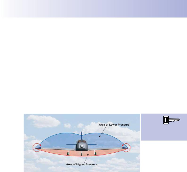
In order to modify the two-dimensional picture of airfow depicted in Figure 5.13, we must take a look at the spanwise pressure distribution around a wing. Spanwise pressure distribution is depicted in Figure 5.14. Around an actual wing, the precise shape of the pressure distribution envelope will depend on the wing plan form and on the angle of attack between the wing and the relative airfow.
Wingtip vortices
are caused by spillage
from the high
pressure area under the wing to the low pressure area above the wing.
Figure 5.14 A representative, spanwise, pressure distribution envelope, showing airflow around the wingtips.
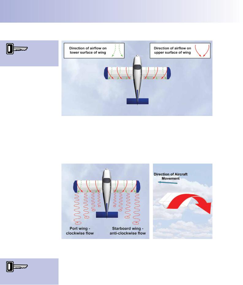
As we have already mentioned, the pressure difference between the regions above and below the wings causes air, at the wing tips, to fow from the region of higher pressure below the wing to the region of lower pressure above the wing. This spillage of air around the wingtips is also depicted in Figure 5.14 and infuences the whole of the airfow around the wing, along the wing’s total span. On the undersurface, because the fow around the wingtips is outwards and upwards, there is a general outward fow across the whole length of the wing’s undersurface towards the wingtips. At the wingtips, on the upper surface, spillage causes a downwards-curling, inwards fow which defects the airfow over the whole length of the wing’s upper surface inwards towards the fuselage. (See Figure 5.15.)
99
Order: 6026
Customer: Oleg Ostapenko E-mail: ostapenko2002@yahoo.com
Customer: Oleg Ostapenko E-mail: ostapenko2002@yahoo.com
CHAPTER 5: DRAG
Wingtip vortices affect
the spanwise flow of air
above and below the wing.
Figure 5.15 Deflection of main airflow spanwise caused by wingtip spillage.
Trailing Edge and Wingtip Vortices.
Where the spanwise defections in the airfow combine with the main longitudinal airfow, at the wing’s trailing edge, they meet at an angle to each other to form vortices at the trailing edge, as depicted by Figure 5.16. When viewed from behind, these vortices will be rotating clockwise from the port (left) wing and anti-clockwise from the starboard (right) wing. The vortex at each wingtip is particularly large and strong.
(See Figure 5.17.)
Wingtip vortices and
trailing edge vortices are
the cause of induced drag.
Figure 5.16 When spanwise deflection meets the |
Figure 5.17 The wingtip vortex is |
main airflow, vortices are formed at the trailing edge. |
particularly large and strong. |
It is the combination of trailing-edge and wingtip vortices which are the cause of induced drag.
Both wingtip and trailing edge vortices will become larger and stronger as the pressure difference between the upper and lower wing surfaces increases. Consequently, if we consider normal operating angles of attack (that is: below the stalling angle of attack), the vortices will increase in size and strength with increasing angle of attack.
100
ID: 3658
Customer: Oleg Ostapenko E-mail: ostapenko2002@yahoo.com Customer: Oleg Ostapenko E-mail: ostapenko2002@yahoo.com
CHAPTER 5: DRAG
This fact is the frst factor in the explanation of why, unlike parasite drag, induced drag, in straight fight, increases as airspeed decreases (increasing angles of attack), and decreases as airspeed increases (decreasing angles of attack).
Additional Downwash Caused by the Wingtip Vortices.
Considering the direction of rotation of the large wingtip vortices, we see that they cause an upwards defection in the airfow on the outside of the wing span and a downwards defection – or downwash - of air within the wingspan, at the trailing edge.
This additional downwash of the airfow must not be confused with the downwash caused by the inherent downwards-turning effect on the airfow by the wing which we discussed in the chapter on lift, and which is vital to the production of lift.
It is the additional downwash, caused by the wingtip vortices, which is the primary cause of induced drag.
Wingtip vortices
increase downwash,
cause the lift
vector to rotate rearwards, and give rise to induced drag.
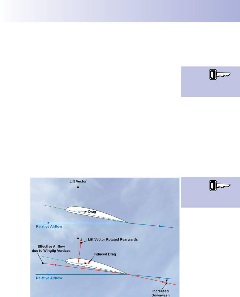
The additional downwash, however, increases the main downwash leaving the trailing edge of the wing. For this reason, both the total reaction and the lift force vector acting perpendicularly to the relative airfow are rotated backwards. This situation is depicted in Figure 5.18. (Note, that Figure 5.18 is a highly simplifed representation of the rearward tilting of the lift force. No airfow is shown, except for one representative line, and no total reaction is shown.) The rotating rearwards of the lift vector under the infuence of the wingtip vortices increases the horizontal component of aerodynamic force (which we originally labelled simply as drag) acting against the direction of motion of the aircraft. It is this increase in the rearwards acting component of the lift force which is the induced drag.
The higher the
angle of attack, the stronger the
wingtip vortices
and the greater the induced drag.
Figure 5.18 The effective airflow is the true airflow.
101
Order: 6026
Customer: Oleg Ostapenko E-mail: ostapenko2002@yahoo.com
Customer: Oleg Ostapenko E-mail: ostapenko2002@yahoo.com
CHAPTER 5: DRAG
So whenever the wings are producing lift, they are also generating induced drag.
In particular, in straight fight, the lower the aircraft’s speed (greater angle of attack) the greater is the induced drag, and the higher the aircraft’s speed, the lower is the induced drag.
|
|
In fact, induced drag is inversely |
|
|
proportional to the square of the |
|
|
aircraft’s velocity, in straight fight. This |
|
|
relationship is shown in Figure 5.19. |
|
|
This is a totally opposite situation to the |
|
|
case of parasite drag which increases |
|
|
as the aircraft’s speed increases. |
|
|
(Parasite drag, you will remember, is |
|
|
directly proportional to the square of |
|
|
the aircraft’s velocity.) |
|
|
The wing tip vortices and, therefore, |
|
|
the induced drag, are largest and most |
|
|
powerful at high angles of attack, and |
|
|
disappear altogether at the zero-lift |
Induced |
Figure 5.19 Induced drag is inversely |
angle of attack; that is, at about -2° for |
drag varies |
proportional to the square of the airspeed. |
a typical light-aircraft wing. |
inversely with the square of
the airspeed.
The Effect of Manoeuvres and Weight on Induced Drag.
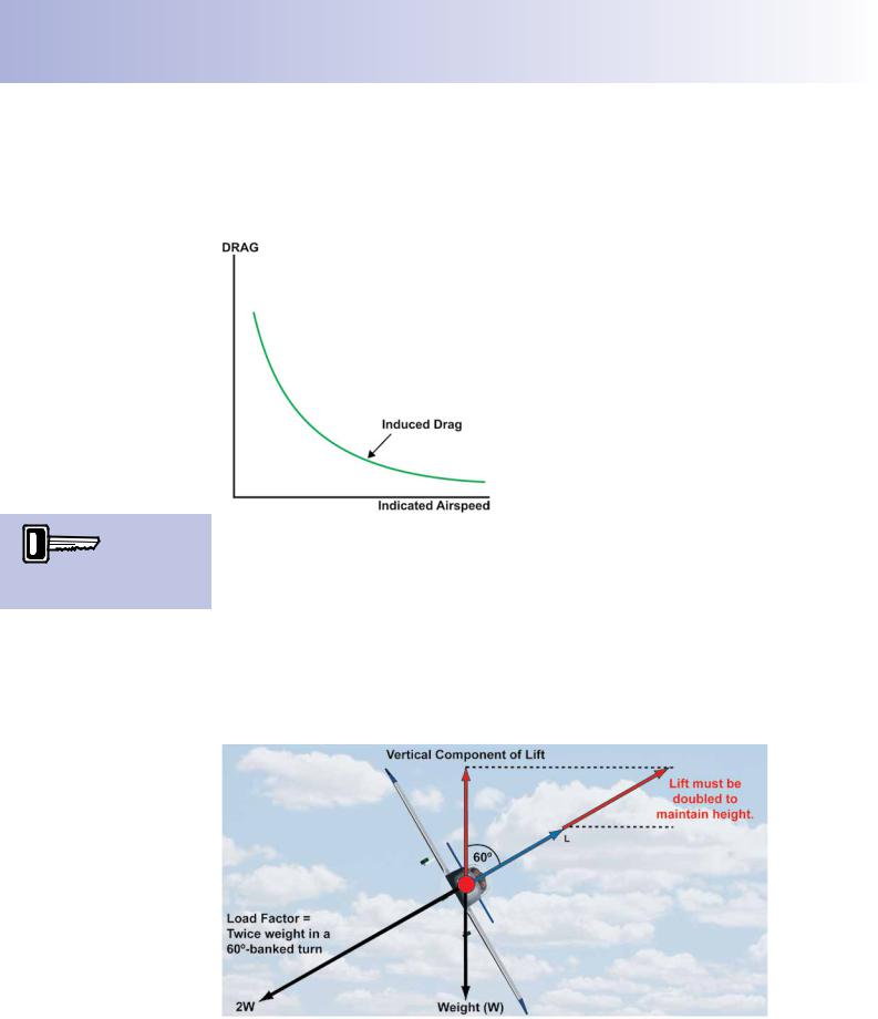
In level turns fown at any given airspeed, the wings have, of course, to create more lift than is required for level fight at the same speed, in order maintain height. To maintain height in a turn, angle of attack (and power) must be increased. Consequently, greater induced drag will be generated in a turn than in straight fight, at the same speed. In a very steep turn, for instance, at a 60º angle of bank, an aircraft wing has to generate twice the lift needed for straight fight. This situation is depicted in Figure 5.20.
Figure 5.20 In a level, 60º-banked turn, lift must be doubled, leading to a significant increase in induced drag.
102
ID: 3658
Customer: Oleg Ostapenko E-mail: ostapenko2002@yahoo.com Customer: Oleg Ostapenko E-mail: ostapenko2002@yahoo.com
CHAPTER 5: DRAG
If speed is not increased, the extra lift needs to be generated by increasing angle of attack (and power). And, so, induced drag, which is inseparable from lift, will also increase even though there has been no increase in speed. The increase in induced drag is, of course, the reason why the pilot has to apply more power in turns, especially in a steep turn, in order to maintain speed and height.
You may have noticed, at air shows, that, when violent manoeuvres are fown by a fghter aircraft, vapour trails can sometimes be seen at the fghter’s wingtips. This is because the pressure at the centre of the wingtip vortices gets so low that the water vapour in the air condenses into visible trails. The vapour trails, so generated, sometimes illustrate dramatically, by their irregular streaming movement, the agitated nature of the vortex fow.
Of course, in turns, when increased lift is required to balance the weight, the inertial reaction to the increased lift force applies an extra load factor on the wings, acting along the same line of action as the lift force but in the opposite direction. The load factor in a balanced 60° banked turn is 2. This load factor is an indication of the apparent increase in weight of the aircraft and its occupants. In a 60°-banked turn, then, the pilot feels that he weighs twice as much as normal and might say, colloquially, that he is “pulling 2g” (‘g’ for gravity).
Similarly, for any given speed, an aircraft in level fight will need to generate more lift if it is carrying a heavy payload than when it is lightly loaded. This means that, at identical speeds, identical aircraft will have to fy at higher angles of attack, the greater their payload. A heavily loaded aircraft, then, will also generate greater induced drag, at a given speed, than an identical aircraft which is lightly loaded.
A heavier
aircraft must fly with increased
angle of attack
at any given airspeed and will generate greater induced drag than a lightly-loaded aircraft.
Summary of the Causes of Induced Drag.
Induced drag is inseparable from the lift-producing function of the wings. Wingtip vortices will be generated as a result of the pressure difference above and below the wings. As the vortices increase in size and strength, they induce an increased, additional downwash which is superimposed on the main, lift-producing downwash. This phenomenon causes the lift vector to rotate rearwards. The rearwards-acting horizontal component arising from the tilting backwards of the lift vector is the induced drag. At low airspeeds and high angles of attack, the vortices are larger and more powerful, the rearwards-tilting of the lift vector is greater, and the induced drag is higher. Induced drag is inversely proportional to the square of the airspeed, reducing as airspeed increases and angle of attack decreases. Compared to straight fight, angle of attack must be increased in steep, level turns, fown at the same speed, in order that the wings may generate the increased lift required to maintain height. Therefore, in steep turns, greater induced drag will act on the aircraft than at the same speed in straight fight.
Methods of Reducing Induced Drag.
A wing of infnite length would, of course, have no wingtips, so there would be no wingtip vortices, no spanwise fow and no induced drag. This hypothetical situation is the situation we were considering when we examined parasite drag. An infnitely long, wingtipless wing is obviously an impossibility. In practice, the best methods of minimising induced drag involve reducing the vortex-generating effects of wings and wingtips. There are several methods of achieving this aim.
103
Order: 6026
Customer: Oleg Ostapenko E-mail: ostapenko2002@yahoo.com
Customer: Oleg Ostapenko E-mail: ostapenko2002@yahoo.com
CHAPTER 5: DRAG
Reducing Induced Drag - Aspect Ratio.
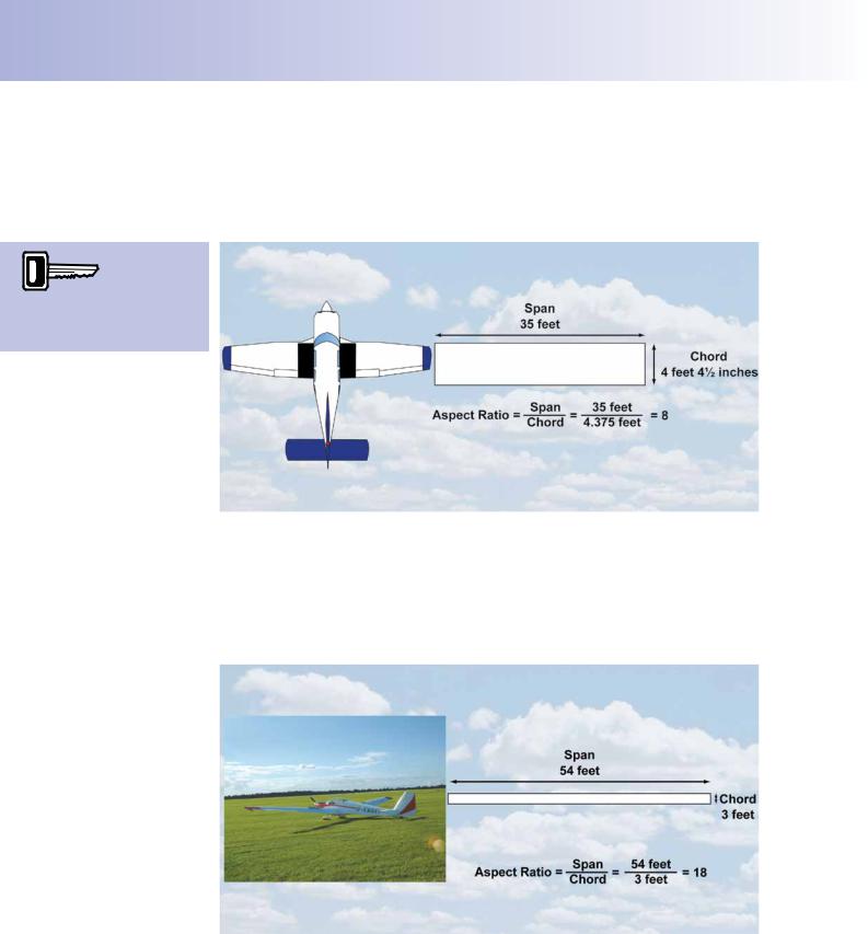
An infnitely long wing, without wingtips, generates no induced drag. The best practical approximation to a wing of infnite length is a wing of high aspect ratio; that is, a wing whose span is great relative to its mean chord. The notion of aspect ratio is illustrated in Figure 5.21.
A high aspect ratio wing
produces less induced drag than a low aspect ratio wing of
the same area.
Figure 5.21 A wing of low aspect ratio.
Both the schematics of simple wing plan-forms in Figures 5.21 and 5.22 have approximately equal wing areas. But the shorter, stubbier wing has a low aspect ratio of 8 whereas the longer, more slender wing has a high aspect ratio of 18. The aircraft illustrated alongside each plan-form may not have these exact aspect ratios in reality, but the illustrations do show how aircraft can have either low or high aspect ratio wings.
Figure 5.22 A wing of high aspect ratio.
A light training aircraft, for instance, might have an aspect ratio of 7 or 8, whereas a touring motor glider could have an aspect ratio of around 14 to 18.
Now, in the design of a wing, area is an important factor in determining what lift the wing can develop (Lift = CL ½ ρ v² S). But a wing of high aspect ratio will generate much less induced drag than a wing of low aspect ratio of equal area.
104
ID: 3658
Customer: Oleg Ostapenko E-mail: ostapenko2002@yahoo.com Customer: Oleg Ostapenko E-mail: ostapenko2002@yahoo.com
CHAPTER 5: DRAG
This is because the high aspect ratio wing is a closer approximation to a wing of infnite length than is a low aspect ratio wing. A high aspect ratio wing has a smaller wingtip of less vortex-generating signifcance than a low aspect ratio wing of equal area. With the high aspect ratio wing, then, there is less spillage of air from the high pressure area below the wing to the low pressure area above it, and, consequently, smaller, less powerful, wingtip vortices are generated, causing less induced drag.
Obviously, the production of very high aspect ratio wings carries with it structural issues for the designer, but the increasing load bearing and fexing qualities of composite materials is overcoming this problem.
The Shape of the Wing’s Plan-form.
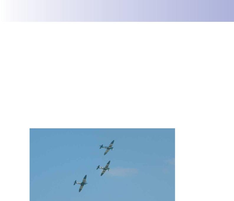
We have established that induced drag is greatest when the wingtip vortices are greatest, so any method of reducing wingtip vortices will reduce induced drag, too. High aspect ratio wings will achieve this reduction in induced drag, as we have just seen. Wings of elliptical plan-form will achieve the same objective of keeping the wingtip small compared to wing span. The Spitfre is, doubtless, the most famous aircraft to be ftted with wings of elliptical plan-form.
Figure 5.23 Spitfires showing elliptical wing plan-form.
Elliptical wings are expensive to produce because of the manufacturing processes required to create the wing. It is more common for aircraft designers to consider tapered wings which also reduce wingtip size, and, thus, vortex strength. Tapered wings are, however, less effective that elliptical wings at reducing induced drag.
Washout.
You should now be totally at ease with the explanation that induced drag is greatest at high angles of attack, because of the increased pressure difference between the airfow above and below the wings, and that the vortices which cause induced drag are strongest at the wingtips. Now, the wingtip angle of attack can be kept lower than the mean angle of attack for the whole wing by constructing the wing with washout. On a wing with washout, the angle of incidence between the wing and the aircraft’s longitudinal axis reduces gradually along the length of the wing, as the wingtip is approached. In other words, the wing is slightly twisted along its span, as illustrated in Figure 5.24, overleaf.
105
Order: 6026
Customer: Oleg Ostapenko E-mail: ostapenko2002@yahoo.com
Customer: Oleg Ostapenko E-mail: ostapenko2002@yahoo.com
CHAPTER 5: DRAG
Washout helps reduce induced drag.
This means that, at any given mean angle of attack for the whole wing, the angle of attack at the wingtip will always be less than the mean, reducing wingtip vortex size and strength, and so reducing induced drag.
Figure 5.24 Washout refers to the reducing angle of incidence from root to tip. Washout also helps to reduce induced drag.
Winglets and Other Wingtip Modifications.
Modifcations to wingtips, designed to minimise spillage from the high to low pressure regions, can also reduce wingtip vortex strength and, thus, induced drag.
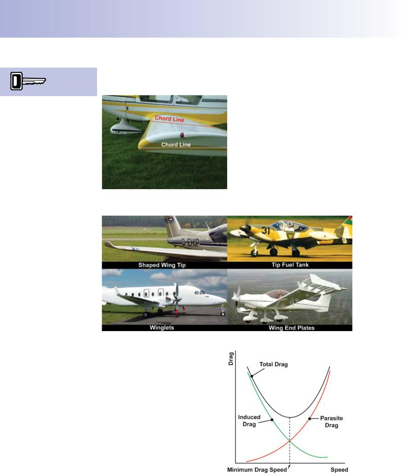
Common wingtip modifcations, some of which are illustrated in Figure 5.25, are: winglets, shaped wingtips, wing end-plates, or wing fences, and wingtip tanks.
Figure 5.25 Wingtip shapes designed to reduce wingtip vortex strength.
TOTAL DRAG.
Total drag as you learnt at the beginning of this chapter is made up of parasite drag and induced drag. You have also learnt that parasite drag increases with the square of the airspeed, whereas induced drag decreases with the square of the airspeed. When we consider an aircraft in any phase of fight: take-off, climb, cruise, descent, or landing, the total drag acting on the aircraft, at any time, will be made up partly of parasite drag and partly of induced drag. Figure 5.26 combines the graphs for the variation of both parasite and induced drag with speed.
Figure 5.26 Graph showing total drag against speed.
106