


21.5. NON-CONTACT TEMPERATURE SENSORS |
1569 |
used in this fashion, a non-contact pyrometer is often referred to as an infrared thermocouple, with the output voltage intended to connect directly to a thermocouple-input instrument such as an indicator, transmitter, recorder, or controller. An example of this usage is the OS-36 line of infrared thermocouples manufactured by Omega.
Infrared thermocouples are manufactured for a narrow range of temperature (most OS-36 models limited to a calibration span of 100 oF or less), their thermopiles designed to produce millivolt signals corresponding to a standard thermocouple type (T, J, K, etc.) over that narrow range.
21.5.2Distance considerations
An interesting and useful characteristic of non-contact pyrometers is that their calibration does not depend on the distance separating the sensor from the target object’s surface25. This is counterintuitive to anyone who has ever stood near an intense radiative heat source: standing in close proximity to a bonfire, for example, results in much hotter skin temperature than standing far away from it. Why wouldn’t a non-contact pyrometer register cooler target temperatures when it was far away, given the fact that infrared radiation from the object spreads out with increased separation distance? The fact that an infrared pyrometer does not su er from this limitation is good for our purposes in measuring temperature, but it doesn’t seem to make sense at first.
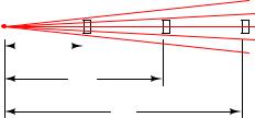
One key to understanding this paradox is to quantify the bonfire experience, where perceived temperature falls o with increased distance. In physics, this is known as the inverse square law : the intensity of radiation falling on an object from a point-source decreases with the square of the distance separating the radiation source from the object. Backing away to twice the distance from a bonfire results in a four-fold decrease in received infrared radiation; backing way to three times the distance results in a nine-fold decrease in received radiation.
25An important caveat to this rule is so long as the target object completely fills the sensor’s field of view (FOV). The reason for this caveat will become clear at the conclusion of the explanation.
1570 |
CHAPTER 21. CONTINUOUS TEMPERATURE MEASUREMENT |
Placing a sensor at three integer distances (x, 2x, and 3x) from a radiation point-source results in relative power levels of 100%, 25% (one-quarter), and 11.1% (one-ninth) falling upon the sensor at those locations, respectively:
|
|
Relative power received at sensors |
|||||||||||
Point-source |
100% |
25% |
11.1% |
||||||||||
of radiation |
|
x |
|
|
|
|
|
|
|
|
|
|
|
|
|
|
|
|
|
|
|
|
|
|
|
||
|
|
|
|
|
|
|
|
||||||
|
|
|
|
|
|
|
|
|
|
|
|
||
2x
3x
This is a basic physical principle for all kinds of radiation, grounded in simple geometry. If we examine the radiation flux emanating from a point-source, we find that it must spread out as it travels in straight lines, and that the spreading-out happens at a rate defined by the square of the distance. An analogy for this phenomenon is to imagine a spherical latex balloon expanding as air is blown into it. The surface area of the balloon is proportional to the square of its radius. Likewise, the radiation flux emanating from a point-source spreads out in straight lines, in all directions, reaching a total area proportional to the square of the distance from the point (center). The total flux measured as a sphere will be the same no matter what the distance from the point-source, but the area it is divided over increases with the square of the distance, and so any object of fixed area backing away from a point-source of radiation encounters a smaller and smaller fraction of that flux.
21.5. NON-CONTACT TEMPERATURE SENSORS |
1571 |
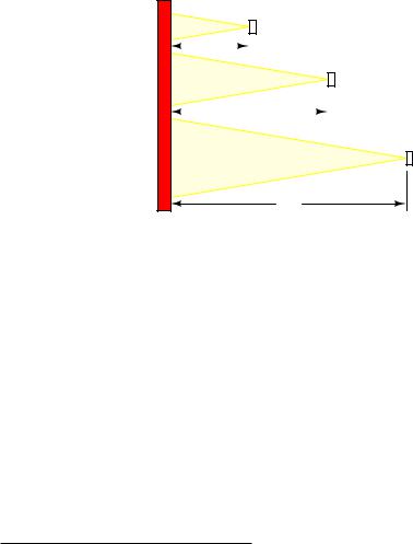
If non-contact pyrometers really were “looking” at a point-source of infrared radiation, their signals would indeed decrease with distance. The saving grace here is that non-contact pyrometers are focused-optic devices, with a definite field of view, and that field of view should always be completely filled by the target object (assumed to be at a uniform temperature). As distance between the pyrometer and the target object changes, the cone-shaped field of view covers a surface area on that object proportional to the square of the distance26 Backing the pyrometer away to twice the distance increases the viewing area on the target object by a factor of four; backing away to three times the distance increases the viewing area nine times:
Target object (e.g. furnace wall)
A |
100% |
|
|
|
|
|
|
||||||||
x |
|
|
|
|
|
|
|
100% |
|
|
|||||
|
|
|
|
|
|
|
|
|
|
||||||
|
|
|
|
|
|||||||||||
4A |
|
|
|
|
|
|
|
|
|||||||
|
|
|
|
|
|
|
|
|
|
||||||
|
|
|
|
|
|
|
|
|
|
|
Relative power received |
||||
|
|
|
|
|
|
|
|
|
|
|
|||||
|
|
|
|
|
|
|
|
|
|
|
|||||
|
|
|
|
2x |
|
|
|
|
by focused pyrometers |
||||||
|
|
|
|
|
|
|
|
|
|
|
|||||
|
|
|
|
|
|
|
|
|
|
100% |
|||||
9A |
|
|
|
|
|
|
|
|
|
|
|
|
|
|
|
|
|
|
|
|
|
|
|
|
|
|
|
|
|
||
3x
So, even though the inverse square law correctly declares that radiation emanating from the hot wall (which may be thought of as a collection of point-sources) decreases in intensity with the square of the distance, this attenuation is perfectly balanced by an increased viewing area of the pyrometer. Doubling the separation distance does result in the flux from any given point on the wall spreading out by a factor of four, but the pyrometer now sees four times as many similar points on the wall as it did previously. So long as all the points within the field of view are uniform in temperature, the result is a perfect cancellation with the pyrometer providing the exact same temperature measurement at any distance from the target.
If the sensor’s field of view expands far enough to capture objects other than the one whose temperature we intend to measure, measurement errors will result. The sensor will now yield a weighted average of all objects within its field of view, and so it is important to ensure that field is limited to cover just the object we intend to measure.
26The field of view (a circle where the viewing “cone” intercepts the flat surface of the object) increases linearly in diameter with increases in distance between the sensor and the object. However, since the area of a circle is
proportional to the square of its diameter (A = πD2 or A = πr2), we may say that the viewing area increases with
4
the square of the distance between the sensor and object.
1572 |
CHAPTER 21. CONTINUOUS TEMPERATURE MEASUREMENT |
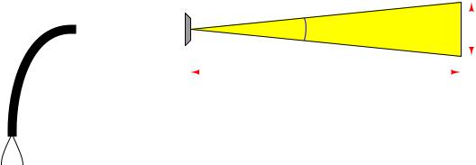
Non-contact sensor fields-of-view are typically specified either as an angle, as a distance ratio, or both. For example, the following illustration shows a non-contact temperature sensor with a 5:1 (approximately 11o) field of view:
5:1 Field-Of-View (FOV) |
|
D |
5 |
|
θ ≈ 11 |
o |
|
|||||||||
11o viewing angle |
|
|
= |
|
|
|
|
|
|
|
|
|
||||
|
d |
|
|
|
|
|
|
|
|
|
||||||
|
1 |
|
|
|
|
|
|
|
||||||||
|
|
|
|
|
|
|
|
|
|
|
|
|
|
|
|
|
|
|
|
|
|
θ |
|
|
|
|
|
|
|
|
|
|
|
|
|
|
|
|
|
|
|
|
|
|
|
|
|
|
|
|
|
|
|
|
|
|
|
|
|
|
|
|
|
|
|
|
|
|
|
|
|
|
|
|
|
|
|
|
|
|
|
|
||
Sensor "head" |
|
|
|
|
|
|
|
|
|
|
|
|
d |
|||
|
|
|
|
|
|
|
|
D |
|
|
|
|
|
|
|
|
|
|
|
|
|
|
|
|
|
|
|
|
|
|
|
||
|
|
|
|
|
|
|
|
|
|
|
|
|
|
|
||
|
|
|
|
|
|
|
|
|
|
|
|
|
|
|
||
|
|
|
|
|
|
|
|
|
|
|
|
|
|
|
||
|
|
|
|
|
|
|
|
|
|
|
|
|
||||
|
|
|
|
|
|
|
|
|
|
|
|
|
|
|||
Cable
The mathematical relationship between viewing angle (θ) and distance ratio (D/d) follows the tangent function:
d |
= |
2 tan θ2 |
|
θ = 2 tan−1 |
|
2D |
D |
|
1 |
|
|
|
d |
|
|
|
|
|
|
|
A sampling of common field-of-view distance ratios and approximate viewing angles appears in this table:
Distance |
Angle |
ratio |
(approximate) |
1:1 |
53o |
2:1 |
30o |
3:1 |
19o |
5:1 |
11o |
7:1 |
8o |
10:1 |
6o |
21.5. NON-CONTACT TEMPERATURE SENSORS |
1573 |
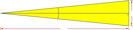
A trigonometric explanation for these equations is shown in the following diagram, where the isosceles field-of-vision triangle is split into two “right” triangles, each one having an adjacent side length of D and an opposite side length of d/2 for angle θ/2:
θ/2
θ/2
d/2
 d
d
d/2
D
Since we know the tangent function is the ratio of opposite to adjacent side lengths for a right triangle, this means the tangent of the half-angle (θ/2) will be equal to the ratio of the opposite side length (d/2) to the adjacent side length (D):
tan |
|
2 |
|
= |
D |
= 2D |
|
|
|
θ |
|
|
d/2 |
|
d |
Solving for the length ratio D/d is now just a matter of algebraically manipulating this equation:
tan |
2 |
|
= |
2D |
||||||||
|
|
|
|
|
θ |
|
|
|
d |
|||
|
2D |
|
|
|
|
1 |
|
|
|
|||
|
|
|
|
= |
|
|
|
|
||||
|
d |
|
tan |
θ |
|
|
||||||
|
D |
= |
|
|
|
|
1 |
2 |
|
|||
|
|
|
|
|
|
|
|
|||||
|
d |
|
2 tan |
θ2 |
|
|
||||||
Solving for the viewing angle (θ) requires another form of manipulation on the basic tangent equation, where we “un-do” the tangent function by using the inverse tangent (or “arctangent”) function:
|
|
tan |
2 |
|
= 2D |
|
|
|
||||||
|
|
|
|
|
|
θ |
|
|
|
d |
|
|
|
|
tan−1 |
tan |
2 |
|
|
= tan−1 |
|
2D |
|||||||
|
|
|
θ |
|
|
|
|
|
|
|
|
|
d |
|
|
|
2 = tan−1 |
|
2D |
|
|
|
|||||||
|
|
θ |
|
|
|
|
|
|
|
d |
|
|
|
|
|
θ = 2 tan−1 |
|
2D |
|
|
|
||||||||
|
|
|
|
|
|
|
|
|
|
d |
|
|
|
|