

2254 |
CHAPTER 28. VARIABLE-SPEED MOTOR CONTROLS |
AC power to the drive circuit be routed anywhere near small-signal or control wiring, because the induced noise will wreak havoc with whatever systems utilize those low-level signals.
RFI noise on the AC power conductors may be mitigated by routing the AC power through filter circuits placed near the drive. The filter circuits block high-frequency noise from propagating back to the rest of the AC power distribution wiring where it may influence other electronic equipment. However, there is little that may be done about the RFI noise between the drive and the motor other than to shield the conductors in well-grounded metallic conduit.
28.3AC motor braking
There are several di erent methods useful for causing an AC induction motor to brake, or slow down:
•DC injection
•Dynamic braking
•Regenerative braking
•Plugging
DC injection uses the technique of energizing the stator windings with low-current DC instead of high-current AC as is the case when the motor runs. Dynamic braking works the motor as a generator, dissipating energy through a resistive load. Regenerative braking also works the motor as a generator, but instead of wasting energy in the form of resistive heating, a regenerating motor drive pumps that energy back into the power supply grid where it may be used by other loads. Lastly, plugging works by applying reverse power to the motor, and is the most aggressive means of bringing any motor to a halt.
All electronic motor braking techniques enjoy the advantage of mechanical simplicity. If the motor itself can be used as a brake, then a separate mechanical brake may not be needed. This simplifies the machinery of a system and potentially reduces maintenance costs.
A significant disadvantage of electronic braking techniques is that they all depend on the proper function of the motor drive, and in some cases the AC line power as well. If a VFD’s braking ability depends on the presence of AC line power, and that line power suddenly is lost, the VFD will have no braking capacity at all! This means a large motor might suddenly have no ability to brake in the event of a power outage or a tripped circuit breaker, which could be a serious safety issue in some applications. In such cases, one must ensure the presence of other (alternative) braking methods to function in the event of line power failure.
28.3. AC MOTOR BRAKING |
2255 |
28.3.1DC injection braking
If a spinning AC induction motor’s stator coils are energized with DC rather than AC, the rotor will find itself spinning inside a stationary magnetic field. This causes currents to be induced in the rotor bars, which in turn causes a braking force to develop in the rotor in accordance with Lenz’s Law. The e ect is exactly opposite of what happens when a motor is energized from a stand-still: there, currents are induced in the rotor bars because the rotor is stationary and the stator field is rotating. This method of braking is quite e ective, with only small amounts of direct current through the stator winding being necessary to cause a large braking torque.
The braking torque produced by DC injection varies directly with the magnitude of the DC injection current, and also directly with the speed of the rotor. This means the braking force created by DC injection tends to diminish as the motor slows down to a stop.
When any motor acts as a brake, the kinetic energy of the motor and the mechanism it attaches to must go somewhere. This is a basic tenet of physics, codified as the Law of Energy Conservation: energy cannot be created or destroyed, only altered in form. When DC injection is used to brake a motor, the braking energy is dissipated in the form of heat by means of the induced currents circulating through the rotor bars and shorting rings. This is something one must be careful to consider when choosing DC injection as a braking method: can the rotor safely dissipate the heat when needed? Repeated braking cycles, especially with little time between cycles, may overheat the rotor and cause damage to the motor.
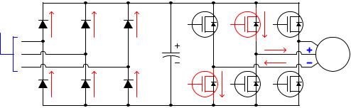
Modern solid-state AC motor drives easily provide DC injection for braking. All they need to do is energize their output transistors in such a way that one or more of the stator windings sees a constant voltage polarity instead of an alternating polarity as is the case when the motor is running. The following diagram shows the power flow into the motor during DC injection:
|
Example showing a VFD injecting DC to the motor |
|
From |
Positive (+) DC bus |
|
three-phase |
||
|
||
AC power |
|
|
source |
|
|
|
AC |
|
|
motor |
|
|
Negative (-) DC bus |
The intensity of the DC injection current may be varied by altering the pulse-width duty cycle of the transistors used to switch the braking current.
2256 |
CHAPTER 28. VARIABLE-SPEED MOTOR CONTROLS |
28.3.2Dynamic braking
If a powered AC induction motor spins at a speed faster than its rotating magnetic field, it acts as a generator: supplying power back to the voltage source, transferring kinetic energy from the spinning rotor and machinery back into electrical power. This makes for an interesting experiment: take an internal combustion engine, steam turbine, water turbine, or some other mechanical prime mover and mechanically force a powered induction motor to spin faster than its synchronous speed (i.e. force it to achieve a negative slip speed). If a power meter is connected between this motor and the AC line power grid, the meter will register negative power (i.e. power flowing from the motor to the grid, rather than from the grid to the motor).
This principle holds true for an induction motor powered by a VFD as well: if the rotor is spun faster than the speed of the rotating magnetic field produced by the VFD, it will act as a generator, sending back more power to the VFD than it receives from the VFD. Since the magnetic field’s rotational speed is variable – thanks to the VFD’s ability to synthesize virtually any desired frequency – it means an induction motor may be made to operate as a generator at almost any speed we desire.
When acting as an electrical generator, an induction motor requires an input of mechanical energy. That is, it will require mechanical e ort to keep the rotor spinning faster than synchronous speed, since the motor naturally “wants” to spin at synchronous speed or slower. This means a generating motor acts as a brake, attempting to slow down whatever is keeping it spinning faster than synchronous speed. This braking e ect is in direct proportion to how much the generated energy is used or dissipated by an electrical load. If we build a VFD to dissipate this energy in a controlled manner, the motor will have the ability to act as a dynamic brake.
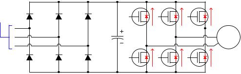
In a VFD circuit, the “reverse” power flow received from the motor takes the form of currents traveling through the reverse-protection diodes placed in parallel with the output transistors. This in turn causes the DC bus filter capacitor to charge, resulting in a raised DC bus voltage:
Generating currents through reverse-protection diodes
From
Positive (+) DC bus
three-phase AC power
source
 AC motor
Negative (-) DC bus
Without a place for this energy to dissipate, however, there will be little braking e ort, and the capacitor will be quickly destroyed by the excessive DC bus voltage. Therefore, in order for dynamic braking to work, the VFD must be equipped with a braking resistor to dissipate the received energy. A special transistor rapidly switched on and o to regulate DC bus voltage ensures the capacitor will not be harmed, and that the braking is e ective.
28.3. AC MOTOR BRAKING |
2257 |
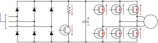
This next schematic diagram shows how a braking resistor and its accompanying transistor could be added to the simple VFD circuit. Once again, the switching circuitry used to turn the braking transistor rapidly on and o has been omitted for simplicity:
|
Braking resistor provides a means of energy dissipation |
|
From |
Positive (+) DC bus |
|
three-phase |
||
|
||
AC power |
|
|
source |
Rbrake |
|
|
AC |
|
|
motor |
|
|
Qbrake |
|
|
Negative (-) DC bus |
The braking transistor switches on in direct proportion to the DC bus voltage. The higher the DC bus voltage, the greater the duty cycle (on time versus total time) of the braking transistor. Thus, the transistor functions as a shunt voltage regulator, placing a controlled load on the DC bus in direct proportion to its degree of over-voltage. This transistor never turns on when the DC bus voltage is within normal (motoring) operating range. It only turns on to clamp DC bus voltage to reasonable levels when the motor spins faster than synchronous speed.
With this braking circuit in place, the only action a VFD must take to dynamically brake an AC induction motor is simply slow down the applied AC frequency to the motor until that frequency is less than the equivalent rotor speed (i.e. create a condition of negative slip speed).
As with DC injection braking, the braking torque created by dynamic braking is a function of magnetic field strength and rotor speed. More precisely, it is a function of the Volts/Hz ratio applied by the VFD to the motor, and the magnitude of the negative slip speed. Braking torque is primarily limited by the braking resistor’s power rating and also the power rating of the VFD. Since the kinetic energy dissipation occurs outside the motor, there is little rotor heating as is the case with DC injection braking.