

Instrumentation Sensors Book
.pdf6.5 Smart Sensors Introduction |
95 |
Vc
VBias |
|
|
− |
Vin |
+ |
Attached to substrate
Anchor |
Flexible arm |
|
− |
|
+ |
Vout
Motion
Polysilicon
Figure 6.17 Topology of a microresonator.
6.5.1Distributed System
The distributed system has a microprocessor integrated with the sensor. This allows direct conversion to a digital signal, conditioning of the signal, generation of a signal for actuator control, and diagnostics. The implementation of smart sensors has many advantages over a central control system [10]. These are as follows:
•The smart sensor takes over the conditioning and control of the sensor signal, reducing the load on the central control system, allowing faster system operation.
•Smart sensors use a common serial bus, eliminating the need for discrete wires to all sensors, greatly reducing wiring cost, large cable ducts, and confusion over lead destination during maintenance or upgrades (especially if lead markers are missing or incorrectly placed).
•Smart sensors have powerful built-in diagnostics, which reduces commissioning and startup costs and maintenance.
•Direct digital control provides high accuracy, not achievable with analog control systems and central processing.
•Uniformity in programming means that the program only has to be learned once, and new devices can be added to the bus on a plug-and-play basis.
•Individual controllers can monitor and control more than one process variable.
•The set points and calibration of a smart sensor are easily changed from the central control computer.
•The cost of smart sensor systems is presently higher than that of conventional systems, but when the cost of maintenance, ease of programming, ease of adding new sensors is taken into account, the long-term cost of smart sensor systems is less.
96 |
Microelectromechanical Devices and Smart Sensors |
The implementation of smart sensors does have some drawbacks. These are:
•If upgrading to smart sensors, care has to be taken when mixing old devices with new sensors, since they may not be compatible.
•If a bus wire fails, the total system is down, which is not the case with discrete wiring. However, with discrete wiring, if one sensor connection fails, it may be necessary to shut the system down. The problem of bus wire failure can be alleviated by the use of a redundant backup bus.
6.5.2Smart Sensors
Smart sensor is a name given to the integration of the sensor with an ADC, a proportional integral and derivative (PID) processor, a DAC for actuator control, and so forth. Such a setup is shown in Figure 6.18 for the mixture of two liquids in a fixed ratio, where the flow rates of both liquids are monitored using differential pressure sensors. The temperatures of the liquids are also monitored to correct the flow rates for density changes and any variations in the sensitivity of the DP cells. All of the sensors in this example can be MEM devices. The electronics in the smart sensor contains all the circuits necessary to interface to the sensor, amplify and condition the signal, and apply proportional, integral, and derivative action (PID) (see Chapter 16). When usage is varying, the signals from the sensors are selected in sequence by the multiplexer (Mux), and are then converted by the ADC into a digital format for the internal processor. After signal evaluation by the processor, the control signals are generated, and the DACs are used to convert the signal back into an analog format for actuator control. Communication between the central control computer and the distributed devices is via a common serial bus. The serial bus, or field bus, is a single twisted pair of leads used to send the set points to the peripheral units and to monitor the status of the peripheral units. This enables the processor in the smart sensor to receive updated information on factors such as set points, gain, operating mode, and so forth; and to send status and diagnostic information back to the central computer [11].
Smart sensors are available for all of the control functions required in process control, such as flow, temperature, level, pressure, and humidity control. The distributed control has many advantages, as already noted.
6.6Summary
Integrated sensors and micromechanical devices were introduced in this chapter. These devices are silicon-based, made using chemical-etching techniques. Properties of integrated silicon devices can be used to accurately measure temperature, light, force, and magnetic field strength. The piezoelectric effect in other materials is used for accurate time generation and in microposition actuators. Integrated micromechanical devices are made using either bulk or surface micromachining techniques. Not only are these devices very small, but conditioning and sensitivity adjustment can be made as an integral part of the sensor, since they are sili- con-based. This has the advantage of noise reduction, high sensitivity, improved reliability, and the ability to add features that normally would require extensive

6.6 Summary |
97 |
|
Mux |
|
|
Smart sensor |
ADC |
Processor |
Serial interface |
|
|
||
|
|
|
|
|
DAC |
DAC |
|
|
S/C |
S/C |
|
DP |
T |
T |
DP |
Liquid A |
Liquid B |
|
|
|
|
|
|
|
|
|
|
|
|
|
|
|
|
|
Valve |
|
|
Valve |
|
||
|
|
|
|
||||
|
|
|
|||||
|
|
|
|
|
Mixture |
|
|
|
|
|
|
|
|
||
Figure 6.18 Smart sensor block diagram.
external circuits. As electronic devices become more cost effective, conventional systems will be replaced with distributed systems using smart sensors, which have a number of advantages in process control facilities, such as reduced loading on the controller, minimized wiring to peripheral units, and simplified expansion with the plug-and-play concept.
References
[1]Humphries, J. T., and L. P. Sheets, Industrial Electronics, 4th ed., Delmar, 1993, pp. 333–336.
[2]Lacanette, K., “Using IC Temperature Sensors to Protect Electronic Systems,” Sensors Magazine, Vol. 14, No. 1, January 1997.
[3]Johnson, C. D., Process Control Instrumentation Technology, 7th ed., Prentice Hall, 2003, pp. 289–297.
[4]Baker, B. C., “Keeping the Signal Clean in Photo-sensing Instrumentation,” Sensors Magazine, Vol. 14, No. 6, June 1997.
[5]Nagy, M. L., C. Apanius, and J. W. Siekkinen, “A User Friendly High-Sensitivity Strain Gauge,” Sensor Magazine, Vol. 18, No. 6, June 2001.
[6]Caruso, M., et al., “A New Perspective on Magnetic Field Sensors,” Sensors Magazine, Vol. 15, No. 12, December 1998.
[7]Lenz, J. E., “A Review of Magnetic Sensors,” Proceedings IEEE, Vol. 78, No. 6, pp. 973–989.
[8]Markus, K. W., V. Dhuler, and R. Cohen, “Smart MEMs: Flip Chip Integration of MEMs and Electronics,” Proceedings Sensors Expo, September 1994.
[9]Ristic, L., Sensor Technology and Devices, 1st ed., Norwood, MA: Artech House, Inc., 1994, pp. 95–144.
[10]Battikha, N. E., The Condensed Handbook of Measurement and Control, 2nd ed., ISA, 2004, pp. 171–173.
[11]Pullen, D., “Overview of Smart Sensor Interfaces,” Proceedings Sensors Expo, September 1994.

C H A P T E R 7
Pressure
7.1Introduction
Pressure is the force per unit area that a liquid or gas exerts on its surroundings, such as the force or pressure of the atmosphere on the surface of the Earth, and the force that liquids exert on the bottom and walls of a container. Pressure is not only an important parameter for process control, but also as an indirect measurement for other parameters. Not only is it important to select the right device for the required range and accuracy, but the device must be immune to contamination and interaction with the fluid being measured. As technology evolves, new and improved methods of accurately measuring pressures are constantly being developed [1].
7.2Pressure Measurement
Pressure units are a measure of force acting over unit area. It is most commonly expressed in pounds per square inch (psi) or sometimes pounds per square foot(psf) in English units; or Pascals (Pa) in metric units, which is the force in Newtons per square meter (N/m2).
Pressure = |
force |
(7.1) |
|
area |
|||
|
|
Example 7.1
The liquid in a container has a total weight of 152 kN, and the container has a 8.9 m2 base. What is the pressure on the base?
Pressure = 152 kPa = 17.1kPa
8.9
7.2.1Hydrostatic Pressure
The pressure at a specific depth in a liquid is termed hydrostatic pressure. The pressure increases as the depth in a liquid increases. This increase is due to the weight of the fluid above the measurement point. The pressure p is given by:
p = h |
(7.2) |
99

100 |
Pressure |
where is the specific weight (lb/ft3 in English units, or N/m3 in SI units), and h is the distance from the surface in compatible units (e.g., ft, in, cm, or m).
Example 7.2
What is the depth in a lake, if the pressure is 0.1 MPa?
Depth = 0.1 MPa 9.8 kN/m3 = 10.2m
The pressure at a given depth in a liquid is independent of the shape of the container or the volume of liquid contained. This is known as the Hydrostatic Paradox. The value of the pressure is a result of the depth and density. The total pressure or forces on the sides of the container depend on its shape, but at a specified depth, the pressure is given by (7.2).
Head is sometimes used as a measure of pressure. It is the pressure in terms of a column of a particular fluid (e.g., a head of 1 ft or 1m of water). For example, the pressure exerted by a 1-ft head of water is 62.4 psf, and the pressure exerted by 1-ft head of glycerin is 78.6 psf. Here again, (7.2) applies.
Example 7.3
What is the pressure at the base of a water tower that has 35m of head?
p = 9.8 kN/m3 × 35m = 343 kPa
7.2.2Specific Gravity
The specific gravity (SG) of a liquid or solid is defined as the density of a material divided by the density of water. SG also can be defined as the specific weight of the material divided by the specific weight of water at a specified temperature. The specific weights and specific gravities of some common materials are given in Table 7.1. The specific gravity of a gas is its density (or specific weight) divided by the density (or specific weight) of air at 60°F and 1 atmospheric pressure (14.7 psia). In the SI system, the density in grams per cubic centimeter or megagrams per cubic meter and the SG have the same value. Both specific weight and density are tempera- ture-dependent parameters, so that the temperature should be specified when they are being measured. SG is a dimensionless value, since it is a ratio.
Table 7.1 Specific Weights and Specific Gravities of Some Common Materials
|
Temperature |
Specific Weight |
Specific Gravity |
|
|
|
lb/ft3 |
kN/m3 |
|
Acetone |
60°F |
49.4 |
7.74 |
0.79 |
Alcohol (ethyl) |
68°F |
49.4 |
7.74 |
0.79 |
Glycerin |
32°F |
78.6 |
12.4 |
1.26 |
Mercury |
60°F |
846.3 |
133 |
13.56 |
Steel |
|
490 |
76.93 |
7.85 |
Water |
39.2°F |
62.43 |
9.8 |
1.0 |
Conversion factors: 1ft3 = 0.028m3; 1 lb = 4.448N; 1 lb/ft3 = 0.157 kN/m3.
7.2 Pressure Measurement |
101 |
Example 7.4
What is the specific gravity of glycerin, if the specific weight of glycerin is 12.4 kN/m3?
SG = 12.4/9.8 = 1.26
7.2.3Units of Measurement
Many industrial processes operate at pressures that are referenced to atmospheric pressure, and are known as gauge pressures. Other processes operate at pressures referenced to a vacuum, or can be referred to as negative gauge pressure. Atmospheric pressure is not a fixed value, but depends on factors such as humidity, height above sea level, temperature, and so forth. The following terms exist when considering atmospheric constants.
1.Atmospheric pressure is measured in pounds per square inch (psi), in the English system.
2.Atmospheric pressure is measured in Pascals (Pa or N/m2), in the SI system.
3.Atmospheric pressure can be stated in inches or centimeters of water.
4.Atmospheric pressure can be stated in inches or millimeters of mercury.
5.Atmosphere (atm) is the equivalent pressure in atmospheres.
6.1 torr = 1 mm mercury, in the metric system.
7.1 bar (1.013 atm) = 100 kPa, in metric system.
Table 7.2 gives the conversions between various pressure measurement units.
Example 7.5
What pressure in psi corresponds to 98.5 kPa?
p = 98.5 kPa (6.895 kPa/psi) = 98.5/6.895 psi = 14.3 psi
Following are the six terms in common use applied to pressure measurements.
1.Total vacuum is zero pressure or lack of pressure, as would be experienced in outer space, and is very difficult to achieve in practice. Vacuum pumps can only approach a true vacuum.
Table 7.2 |
Pressure Conversions |
|
|
|
|
|
|
Water |
|
Mercury** |
|
kPa |
psi |
|
in# |
cm* |
mm |
in |
|
|
1 psi |
27.7 |
70.3 |
51.7 |
2.04 |
6.895 |
1 |
1 psf |
0.19 |
0.488 |
0.359 |
0.014 |
0.048 |
0.007 |
1 kPa |
4.015 |
10.2 |
7.5 |
0.295 |
1 |
0.145 |
1 atm |
407.2 |
1034 |
761 |
29.96 |
101.3 |
14.7 |
1 torr |
0.535 |
1.36 |
1 |
0.04 |
0.133 |
0.019 |
1 millibar |
0.401 |
1.02 |
0.75 |
0.029 |
0.1 |
0.014 |
#at 39°F *at 4°C **Mercury at 0°C
102 |
Pressure |
2.Atmospheric pressure is the pressure on the Earth’s surface, due to the weight of the gases in the Earth’s atmosphere (14.7 psi or 101.36 kPa absolute). The pressure decreases above sea level. For example, at an elevation of 5,000 ft, it has dropped to approximately 12.2 psi (84.122 kPa).
3.Absolute pressure is the pressure measured with respect to a vacuum, and is expressed in psia or kPa(a). Note the use of a and g when referencing the pressure to absolute and gauge.
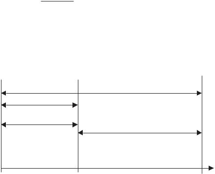
4.Gauge pressure is the pressure measured with respect to atmospheric pressure, and is normally expressed in psig or kPa(g). Figure 7.1 shows graphically the relation between atmospheric, gauge, and absolute pressures.
5.Vacuum is a pressure between total vacuum and normal atmospheric pressure. Pressures less than atmospheric pressure are often referred to as “negative gauge,” and indicated by an amount below atmospheric pressure. As an example, −5 psig corresponds to 9.7 psia.
6.Differential pressure is the pressure measured with respect to another pressure, and is expressed as the difference between the two values. This represents two points in a pressure or flow system, and is referred to as the “delta p,” or ∆p.
Example 7.6
The atmospheric pressure is 14.5 psi. If the absolute pressure is 2,865.6 psfa, what is the gauge pressure?
Gauge pressure = 28656. psfa − 145. psi = 199.psia − 145. psi = 5.4psig 144
Example 7.7
What is the gauge pressure in (a) kPa, and (b) N/cm2, at a distance 5.5 ft below the surface of a column of water?
Absolute zero |
Standard atmospheric pressure |
total vacuum |
|
Absolute pressure at point of interest |
|
Vacuum |
Pressure due to atmosphere |
|
|
Gauge pressure at point of interest |
0 psia |
Pressure |
0 psig – 0kPa(g) |
|
0 kPa(a) |
14.7 psig – 101.3kPa(g) |
Figure 7.1 Illustration of gauge pressure versus absolute pressure.

7.2 Pressure Measurement |
103 |
(a)p = 9.8(5.5/3.28) kPa = 9.8 × 1.68 kPa = 16.4 kPa(g)
(b)p = 16.4 N/m2 = 16.4/10,000 N/cm2 = 1.64 × 10⁻³ N/cm2(g)
The pressure in this case is the gauge pressure [i.e., kPa(g)]. To get the total pressure, the pressure of the atmosphere must be taken into account. The total pressure (absolute) in this case is 9.8 + 101.3 = 111.1 kPa(a). The g and a should be used where possible to avoid confusion. In the case of psi and psf, this becomes psig and psfg, or psia and psfa. In the case of kPa, use kPa(a) or kPa(g). It also should be noted that if glycerin were used instead of water, then the pressure would be 1.26 times higher, since its specific gravity is 1.26.
7.2.4Buoyancy
Buoyancy is the upward force exerted on an object immersed or floating in a liquid. The weight is less than it is in air, due to the weight of the displaced fluid. The upward force on the object causes the weight loss, called the buoyant force, and is given by:
B = V |
(7.3) |
where B is the buoyant force in pounds,  is the specific weight in pounds per cubic foot, and V is the volume of the displaced liquid in cubic feet. If working in SI units, then B is in newtons,
  is in newtons per cubic meter, and V is in cubic meters.
In Figure 7.2, items a, b, c, and d, are the same size, and the buoyancy forces on a and c are the same, although their depths are different. There is no buoyant force on d, since the liquid cannot get under it to produce the buoyant force. The buoyant force on b is one-half that on a and c, since only one-half of the object is submerged.
Example 7.8
What is the buoyant force on a plastic cube with 2.5m sides, floating in water, if three-quarters of the block is submerged?
B = 9.8 kN/m3 × 2.5m × 2.5m × 2.5m × 3/4 = 114.8 kN
b
c
a
d
Figure 7.2 Immersed object to demonstrate buoyancy.

104 |
Pressure |
Example 7.9
What is the apparent weight of a 3.7m3 block of wood totally immersed in acetone? Assume the specific weight of wood is 8.5 kN/m3.
Weight of wood in air = 3.7 × 8.5 kN = 31.45 kN
Buoyant force on wood = 3.7 × 7.74 kN = 28.64 kN
Apparent weight = 31.45 − 28.64 = 2.81 kN (287 kg)
Pascal’s Law states that the pressure applied to an enclosed liquid (or gas) is transmitted to all parts of the fluid and to the walls of the container. This is demonstrated in the hydraulic press in Figure 7.3. A force of FS exerted on the small piston (ignoring friction) will exert a pressure in the fluid given by:
p = |
FS |
(7.4) |
|
AS
where AS is the cross-sectional area of the smaller piston.
Since the pressure is transmitted through the liquid to the second cylinder, according to Pascal’s Law, the force on the larger piston (FL) is given by:
FL = pAL |
(7.5) |
where AL is the cross-sectional area of the large piston (assuming the pistons are at the same level), from which:
FL = |
ALFS |
(7.6) |
|
AS |
|||
|
|
It can be seen that the force FL is magnified by the ratio of the piston areas. This principle is used extensively in hoists, hydraulic equipment, and so forth.
Example 7.10
In Figure 7.3, if the area of the small piston AS is 8.2 in2,and the area of the large piston AL is 2.3 ft2, what is the force FL on the large piston, if the force FS on the small piston is 25N?
FS
Figure 7.3 Diagram of a hydraulic press.