

книги / Организация закачки воды. Система поддержания пластового давления
.pdfTable 1
Parameters of Hydraulic Seal of Sediment Ponds
|
Layer |
|
Hydraulic seal type |
|
||
Description |
|
|
|
|
||
|
Asbestos |
|
|
|||
thickness, |
|
Asbestos |
|
|||
of layer |
Clay seal |
belt and |
Polyethylene |
|||
mm |
felt |
|||||
|
|
bitumen |
|
|||
|
|
|
|
|
||
|
|
|
|
|
|
|
1. Reinforced- |
100 |
+ |
+ |
+ |
+ |
|
concrete slab |
||||||
|
|
|
|
|
||
|
|
|
|
|
|
|
2. Crushed stone |
100 |
+ |
– |
– |
– |
|
|
|
|
|
|
|
|
3. Sandy ground |
500 |
+ |
– |
– |
– |
|
|
|
|
|
|
|
|
4.Clayey ground |
750 |
(+) |
– |
– |
– |
|
(screen) |
||||||
|
|
|
|
|
||
|
|
|
|
|
|
|
5. Cement screed |
20 |
– |
+ |
+ |
– |
|
|
|
|
|
|
|
|
6. Three layers of as- |
– – – |
– |
(+) |
(+) |
– |
|
bestos felt (screen) |
||||||
|
|
|
|
|
||
|
|
|
|
|
|
|
7. Cement grout |
20 |
– |
+ |
+ |
– |
|
|
|
|
|
|
|
|
8. Concrete bedding |
100 |
– |
+ |
+ |
– |
|
|
|
|
|
|
|
|
9. Crushed stone with |
100 |
– |
(+) |
– |
– |
|
bitumen impregnation |
||||||
|
|
|
|
|
||
|
|
|
|
|
|
|
10. Ground with bi- |
|
|
|
|
|
|
tumen treatment |
200 |
– |
(+) |
– |
– |
|
(screen) |
|
|
|
|
|
|
|
|
|
|
|
|
|
11. Packed soil |
– – – |
– |
+ |
+ |
– |
|
|
|
|
|
|
|
|
12.Packed crushed |
100 |
– |
– |
+ |
– |
|
stone |
||||||
|
|
|
|
|
||
|
|
|
|
|
|
|
13. Sandy ground |
200 |
– |
– |
– |
+ |
|
|
|
|
|
|
|
|
14. Polyethylene film |
0.2 |
– |
– |
– |
(+) |
|
(screen) |
||||||
|
|
|
|
|
||
|
|
|
|
|
|
|
15. Sterilized packed |
– – – |
– |
– |
– |
+ |
|
ground |
||||||
|
|
|
|
|
||
|
|
|
|
|
|
|
16. Number of hy- |
– |
4 |
8 |
7 |
4 |
|
draulic seal layers |
||||||
|
|
|
|
|
||
|
|
|
|
|
|
|
Total thickness of hy- |
– |
1.45 |
0.54 |
0.34 |
0.3 |
|
draulic seal |
||||||
|
|
|
|
|
||
|
|
|
|
|
|
|
31
The need to allot large areas, difficulty in collecting oil from the sediment pond surface, aging of trapped oil, gas pollution of the environment calls for modernization of the existing facilities on one hand and for withdrawal of them from the oil production practice on the other. As a possible alternative there may be a construction of “fast” sediment ponds and oil traps.
In the latter case, the process of waste water treatment can be accelerated by passing it through a water-repellent medium, i.e., by combining the settling-down process with the process of filtration. As a water-repellent medium, it is recommended to use water-repellent expended perlite.
When adapting the given method to the formation waste water purification conditions, one should bear in mind the following:
–filter for cleaning the pressing water is designed for one-time use;
–method of collecting and removing oil from the water surface is not workable;
–basins or sumps are required;
–the problem of disposal of oil-saturated filters has not been solved yet; evidently, their burning is not acceptable;
–there is not technology for regeneration of filters.
All methods and technical means for treatment and purification of formation waste waters are realized in different process flow diagrams. The most widely applied are the following:
1)initial water separation plants;
2)waste water purification systems as part of a complex plant for field product treatment;
3)formation water purification plants in the system of restoration (increase) of injectability of injection wells;
4)complex plants for purification of field waste waters.
32
Initial Formation Waste Water Separation Plants
In recent years, initial formation water separation plants (IWSP) have found a sufficiently wide application in the petroleum engineering which fit into the oil production system on one side and into the FPM system on the other.
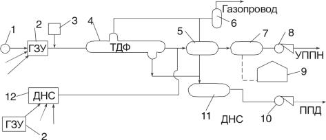
These plants can employ different configurations. Figs 7 to 9 show the configurations which have been realized at a number of facilities on the oil fields in the Volga River basin. According to the configuration “a” (fig. 7), the product is fed directly through the group metering stations (GMS) of oil wells to the IWSP in two flows. The first flow comprises a three-phase medium (oil, water, gas) applied directly from the GMS to a three-phase phase divider (TPD) which is the basic element of the IWSP, where gas separation and initial water separation take place. Demulsifying compound should be introduced, if possible, at initial points of the process flow, i.e., either in the GMS pipeline of the IWSP, or on the group measuring station proper, or in the oil well. With the agent being introduced in close proximity to the three-phase phase divider, the batcher shall be provided with an additional device for its dispersion in the flow.
Fig.7. Initial water separation plant (IWSP) (diagram “a”):
1 – oil-producing well; 2 – group metering station; 3 – batcher; 4 – three-phase phase divider; 5 – separator; 6 – desiccator; 7 – oil accumulator; 8 – oil pump;
9 – dump reservoir; 10 – water pump; 11 – water accumulator; 12 – booster pump station (BPS)
Gas pipeline
ДНС = BPS; ГЗУ = GMS; ППД = FPM; УППН = OTF (oil treatment facilities)
33
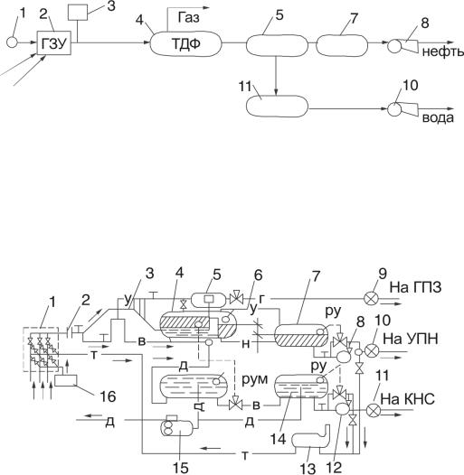
Fig. 8. Initial water separation plant (IWSP) (diagram “b”)
ГЗУ = GMS; ТДФ = TPD (three-phase phase diviver).
Fig. 9. Combined phase separation and initial water separation process flow diagram:
1 – distribution assembly; 2 – stilling header; 3 – preliminary distribution assembly;
4 – gas-and-water separator; 5 – gas separator; 6 – water settler; 7 – buffer tank for oil;
8 – BPS; 9 to 11 – gas, oil and water metering stations, respectively; 12 – water pump station;
13 – heating unit; 14 – buffer tank for water; 15 – drain tank; 16 – agent block;
н – oil; в – water; г – gas: д – drainage; т – heat carrier; у – gas equalizer line;
РУ – interphase level controller
На ГПЗ = To GPP (gas processing plant)
На УПН = To OTF (oil treatment facilities)
На КНС = To GPS (group pumping station)
34
Purification of Formation Waste Waters at Oil Treatment Facilities
The majority of modern systems for purification of formation waste waters (FWW), which are functionally and territorially combined with a field product treatment plant, can be classified as follows:
Diagram 1. Treatment of the FWW by use of vertical steel tanks – settles (VTS). Diagram 2. Treatment of the FWW by settling down in the VTS and by fil-
tering in pressure filters.
Diagram 3. Treatment of the FWW in head settlers (HS).
Diagram 4. Treatment of the FWW by settling down in the HS and by filtering in pressure filters.
Diagram 5. Open purification of the FWW.
Diagram 6. Treatment of the FWW by settling down in oil traps and ponds with subsequent pressure filtration.
In addition to the above-said technologies of FWW purification, various special technologies are also used at the oil, water and gas treatment facilities among which it is necessary to distinguish two as follows:
Technology 1 intended for treatment of mixed formation waters fed from different production horizons, e.g., from Devonian and coal-measures horizons.
Technology 2 intended for treatment and purification of field product with a high content of mechanical admixtures and high-density components such as iron sulfide.
The need for use of special technologies and schemes for the FWW purification is increasing in connection with return to formation product draw-off from the upper horizons. Construction of parallel plants for treatment of products of two and more horizons on one area are not generally efficient. The combined technologies are finding application on the oil fields of the Volga-Ural region.
During designing and operating the FWW purification systems, which are part of the oil treatment facilities, it is necessary to take into consideration the influence of adjacent facilities such as technological (oil) reservoirs and means of disposal, including commercial, hydrocarbon, and other admixtures.
35
Purification of Formation Waste Waters at Injection Wells
Purification of the FWW directly at the injection wells is carried out most often in order to restore their injectability. The FWW is carried up from the injection well cavity and from the polluted bottomhole zone of the formation in the wellspring mode. Mechanical admixtures and hydrocarbon components are usually separated by use of three schemes.
According to the first scheme, the contaminated water is drawn off directly from the injection well, purified on a mobile water purification plant and injected back into the formation. The mobile water purification plant comprises a buffer tank, filters, and a high-pressure pump with a diesel-engine drive.
According to the second scheme, a reservoir-catch basin or a FWW catch basin is constructed at each injection well with a total capacity of about 250 m3 with a water-proof bottom and walls. From the catch basins, wash water is taken out by tank trucks to the base plants for treatment of formation waste water and to the oil and water treatment plants (O&WTP).
According to the third scheme, the polluted formation waste waters are fed under the well-spring pressure to treatment facilities of the O&WTP. In this case, special water conduits are constructed or the second lines of working water conduits are employed on the sections from a water distributing point (WDP) to the GPS (group pumping station) and from the GPS to the O&WTP.
6. BLOCKED GROUP PUMPING STATIONS, BASIC
COMPONENTS AND FUNCTIONING
For injecting water, use if made of pumping stations and plants based mainly on centrifugal piston-type pumping units.
Group pumping stations (GPS) operate into several tens of injection wells. The most widely used are group pumping stations of blocked type. The
blocked group pumping stations (BGPS) are based generally on centrifugal pumps, types ЦНС-180 and ЦНС-500. The composition of the BGPS depending on the type of blocks is given in Table 2 and on the number of pumps, in Table 3.
36
|
|
|
|
|
|
|
Table 2 |
|
|
|
Composition of BGPS Units |
|
|
||||
|
|
|
|
|
|
|
|
|
|
|
|
Description and code of blocks |
|
|
|||
|
|
|
|
|
|
|
|
|
BGPS type |
Pumping |
Low-voltage |
Pressure |
Drain |
Service |
Distributing |
Waste wa- |
|
block |
equipment |
pipe header |
pumps |
block |
device block |
ter reser- |
||
|
||||||||
|
(НБ) |
block (БА) |
(БГ) |
block (БД) |
(БО) |
(РУ**) |
voir** |
|
|
|
|
|
|
|
|
|
|
BGPS 1x100 |
1 |
1 |
1 |
– |
– |
1 |
1 |
|
|
|
|
|
|
|
|
|
|
BGPS 1x150 |
1 |
1 |
1 |
– |
– |
1 |
1 |
|
|
|
|
|
|
|
|
|
|
BGPS 1x200 |
1 |
1 |
1 |
– |
– |
1 |
1 |
|
|
|
|
|
|
|
|
|
|
BGPS 2x100 |
2 |
1 |
1 |
– |
– |
1 |
1 |
|
|
|
|
|
|
|
|
|
|
BGPS 2x100* |
2 |
1 |
1 |
1 |
– |
1 |
1 |
|
|
|
|
|
|
|
|
|
|
BGPS 2x150 |
2 |
1 |
1 |
– |
– |
1 |
1 |
|
|
|
|
|
|
|
|
|
|
BGPS 2x150* |
2 |
1 |
1 |
1 |
– |
1 |
1 |
|
|
|
|
|
|
|
|
|
|
BGPS 2x200 |
2 |
1 |
1 |
– |
– |
1 |
1 |
|
|
|
|
|
|
|
|
|
|
BGPS 2x200* |
2 |
1 |
1 |
1 |
– |
1 |
1 |
|
|
|
|
|
|
|
|
|
|
BGPS 3x100 |
3 |
1 |
2 |
– |
– |
1 |
1 |
|
|
|
|
|
|
|
|
|
|
BGPS 3x100* |
3 |
1 |
2 |
1 |
– |
1 |
1 |
|
|
|
|
|
|
|
|
|
|
BGPS 3x150 |
3 |
1 |
2 |
– |
– |
1 |
1 |
|
|
|
|
|
|
|
|
|
|
BGPS 3x150* |
3 |
1 |
2 |
1 |
– |
1 |
1 |
|
|
|
|
|
|
|
|
|
|
BGPS 3x200 |
3 |
1 |
2 |
– |
– |
1 |
1 |
|
|
|
|
|
|
|
|
|
|
BGPS 3x200* |
3 |
1 |
2 |
1 |
– |
1 |
1 |
|
|
|
|
|
|
|
|
|
|
BGPS 4x100 |
4 |
1 |
2 |
– |
– |
1 |
1 |
|
|
|
|
|
|
|
|
|
|
BGPS 4x100* |
4 |
1 |
2 |
1 |
– |
1 |
1 |
|
|
|
|
|
|
|
|
|
|
BGPS 4x150 |
4 |
1 |
2 |
– |
– |
1 |
1 |
|
|
|
|
|
|
|
|
|
|
BGPS 4x150* |
4 |
1 |
2 |
1 |
– |
1 |
1 |
|
|
|
|
|
|
|
|
|
|
BGPS 4x200 |
4 |
1 |
2 |
– |
– |
1 |
1 |
|
|
|
|
|
|
|
|
|
|
BGPS 4x200* |
4 |
1 |
2 |
1 |
– |
1 |
1 |
|
|
|
|
|
|
|
|
|
|
BGPS 2x500 |
2 |
1 |
1** |
– |
1 |
1 |
– |
|
|
|
|
|
|
|
|
|
|
BGPS 3x500 |
3 |
1 |
1** |
– |
1 |
1 |
– |
|
|
|
|
|
|
|
|
|
|
BGPS 4x500 |
4 |
1 |
1** |
– |
1 |
1 |
– |
|
|
|
|
|
|
|
|
|
|
*With closed ventilation cycle.
**Not included into the Manufacturer’s delivery set.
37

Table 3
Dependence of Number of Blocks on Number of Pumps
Description of block |
Block |
Number of blocks at number of pumps included |
||||
|
|
into BGPS |
|
|||
included into BGPS |
code |
|
|
|
||
|
|
|
|
|
||
1 |
2 |
|
3 |
4 |
||
|
|
|
||||
|
|
|
|
|
|
|
Pump block, extreme |
НБ-1 |
1 |
|
|
|
|
|
|
|
|
|
|
|
Pump block, middle |
НБ-2 |
– |
1 |
|
2 |
3 |
|
|
|
|
|
|
|
Low-voltage equipment |
A-1 |
1 |
1 |
|
1 |
1 |
block |
A-2 |
1 |
1 |
|
1 |
1 |
|
|
|
|
|
|
|
Pressure pipe header |
БГ-1 |
1 |
1 |
|
2 |
2 |
block |
|
|||||
|
|
|
|
|
|
|
|
|
|
|
|
|
|
Distribution block |
РУ-6КВ |
1 |
1 |
|
1 |
1 |
|
|
|
|
|
|
|
Inducer block |
БВ-1 |
– |
1 |
|
1 |
1 |
|
|
|
|
|
|
|
Table 4 gives technical characteristics of four main groups of blocked group pumping stations: BGPS x100, BGPS x150, BGPS x200, BGPS x500.
A pump block comprises as main elements the centrifugal multi-stage sectional pumps, types ЦНС-180 or ЦНС-500, the main characteristics of which, depending on the number of stages, are given in Table 3. The pump block comprises also a pump electric drive (a synchronous motor, series СТД, with static excitation, or an asynchronous motor, series APM), a lubricating unit for the pumping plant, an axial fan with electric drive, a local control station with an emergency shut-down button, instrumentation, shut-off and control valves of the pumping plant, process pipelines.
A BGPS comprises pump blocks of two types: НБ-1 (extreme pump block) and НБ-2 (middle pump block). The presence of a НБ-1 pump block is mandatory regardless of the number of pumping plants in the BGPS. The two pump blocks differ in the design of their shelters.
The suction line of the pumping plant is equipped with a screen filter and a hand-operated gate valve, type ЗКЛ2; the delivery line is equipped with a nonreturn valve and an electrically-driven gate valve, type B-403.
A pressure pipe header block (БГ), intended for metering and distributing the process liquid fed from the pump over the pressure pipelines, is arranged in a separate all-metal cubicle at a distance of not less than 10 m from the other blocks.
38
This block comprises a distribution header, a back-flushing header, a control point, a flow meter with an orifice, a shut-off valve, a fan, a maintenance floor, an electric heater.
In addition to blocked group pumping stations, the FPM systems of oil-and- gas production divisions employ group pumping stations based on pumps of other types, brief characteristics of which are given in Table 2.4.
Among perspective equipment are hydraulic modular pumps with an “absolute” controllability of flow rate.
|
|
|
|
Table 4 |
|
|
BGPS Technical Characteristics |
|
|||
|
|
|
|
|
|
Parameters |
|
BGPS group |
|
||
|
|
|
|
||
BGPS x100 |
BGPS x150 |
BGPS x200 |
BGPS x500 |
||
|
|||||
|
|
|
|
|
|
Type of basic pump |
ЦНС-180-1050 |
ЦНС-180-1422 |
ЦНС-180-1900 |
ЦНС-500-1900 |
|
|
|
|
|
|
|
Rated pumping capacity, |
|
180 |
|
|
|
m3/h |
|
|
|
||
|
|
|
|
||
|
|
|
|
|
|
Delivery pressure, MPa |
10 |
14 |
18.6 |
18.6 |
|
|
|
|
|
|
|
Suction line permissible |
|
2.7 |
2.7 |
|
|
pressure, MPa |
|
|
|||
|
|
|
|
||
|
|
|
|
|
|
Cooling system pressure, |
|
0.2 |
0.2 |
|
|
MPa |
|
|
|||
|
|
|
|
||
|
|
|
|
|
|
Pressure in the system |
|
|
|
|
|
drawing off water from seal |
|
0.4 |
0.4 |
|
|
glands and thrust bearing, |
|
|
|||
|
|
|
|
||
MPa |
|
|
|
|
|
|
|
|
|
|
|
Maximum consumption of |
|
|
|
|
|
water for cooling and back- |
25 |
30 |
30 |
|
|
ing the seal glands, m3/h |
|
|
|
|
|
|
|
|
|
|
|
Temperature of pumped in |
|
8 to 40 |
8 to 40 |
|
|
water, ºC |
|
|
|||
|
|
|
|
||
|
|
|
|
|
|
Nominal power require- |
675 |
970 |
1150 |
3340 |
|
ment of pump, kW |
|||||
|
|
|
|
||
|
|
|
|
|
|
Electric drive power, kW |
800 |
1250 |
1600 |
4000 |
|
|
|
|
|
|
|
Rotation frequency, rev/min |
|
3000 |
3000 |
|
|
|
|
|
|
|
|
Supply voltage of electric |
|
6 (10) |
6 (10) |
|
|
drive, kV |
|
|
|||
|
|
|
|
||
|
|
|
|
|
|
39

Voltage in the network of |
|
|
380/220 |
380/220 |
|
|
auxiliary equipment, V |
|
|
|
|
||
|
|
|
|
|
|
|
|
|
|
|
|
|
|
Electric motor current |
|
|
Three-phase, alternating, 50 Hz |
|
||
|
|
|
|
|
|
|
Oil system pressure, MPa |
|
|
0.3 |
0.3 |
|
|
|
|
|
|
|
|
|
Oil consumption per one |
|
|
2.1 |
2.1 |
|
|
plant, l/h |
|
|
|
|
||
|
|
|
|
|
|
|
|
|
|
|
|
|
|
Reference size of pipes, |
|
|
|
|
|
|
mm: |
|
|
|
|
|
|
|
|
|
|
|
|
|
Suction pipes |
|
|
150 |
150 |
|
|
|
|
|
|
|
|
|
Delivery pipes |
|
|
125 |
125 |
|
|
|
|
|
|
|
|
|
Suction pipes of pipe |
|
|
200 |
200 |
|
|
header block |
|
|
|
|
||
|
|
|
|
|
|
|
|
|
|
|
|
|
|
Outlet pipes of pipe heater |
|
|
100 |
100 |
|
|
block |
|
|
|
|
||
|
|
|
|
|
|
|
|
|
|
|
|
|
|
Reference size of cooling |
|
|
|
|
|
|
water inlet and outlet pipes, |
|
|
|
|
|
|
mm: |
|
|
|
|
|
|
|
|
|
|
|
|
|
At open ventilation cycle |
50 |
|
100 |
100 |
|
– |
(OVC) |
|
|
||||
|
|
|
|
|
|
|
|
|
|
|
|
|
|
At closed ventilation cycle |
|
|
100 |
100 |
|
|
(CVC) |
|
|
|
|
||
|
|
|
|
|
|
|
|
|
|
|
|
|
|
Overall dimensions of |
|
|
|
|
|
|
pump blocks, mm: |
|
|
|
|
|
|
|
|
|
|
|
|
|
Length |
|
|
9804 |
9804 |
|
12000 |
|
|
|
|
|
|
|
Width |
|
|
3102 |
3102 |
|
5000 |
|
|
|
|
|
|
|
Height |
|
|
2992 |
2992 |
|
5100 |
|
|
|
|
|
|
|
The largest mass of pump |
|
|
|
|
|
|
block, kg: |
|
|
|
|
|
|
|
|
|
|
|
|
|
At OVC |
18,000 |
|
21,900 |
23,000 |
|
404,000 |
|
|
|
|
|
|
|
At CVC |
19,800 |
|
22,600 |
24,400 |
|
|
|
|
|
|
|
|
|
Mass of pipe header block, |
|
|
13, 470 |
13,470 |
|
– |
kg |
|
|
|
|||
|
|
|
|
|
|
|
|
|
|
|
|
|
|
Heating source: |
|
|
|
|
|
|
|
|
|
|
|
||
Standard source |
Secondary heat of equipment |
Electrical |
||||
|
|
|
|
|
||
Stand-by source |
|
Electrical |
Same |
|
||
|
|
|
|
|
||
Ventilation |
Suction-and-exhaust, mechani- |
– |
|
|||
cally initiated |
|
|||||
|
|
|
|
|||
|
|
|
|
|
||
Automation |
|
Complex |
– |
|
||
|
|
|
|
|
|
|
40