

02 BOPs / Woods D.R 2008 rules-of-thumb-in-Engineering-practice (epdf.tips)
.pdf1.6 Rules of Thumb about the Context for a Chemical Process: Heterogenous Phase contacting 11
Control valves: “Leaks”: erosion/[corrosion]*/gaskets, packing or bolts at temperatures, pressures and fluids that differ from design. “Cannot control low flowrate”: miscalibration/buildup of rust, scale, dirt. “Cannot stop flow”: miscalibration/ damaged seat or plug. “Excessive flow”: excessive Dp. “Slow response”: restricted air to actuator/dirty air filters. “Noise”: [cavitation]*/compressible flow. “Poor valve action:” dirt in instrument air/sticky valve stem/packing gland too tight/faulty valve positioner. “Equipment suddenly underperforms”: bypass partially or fully open.
Transmitters: “Erratic or fluctuating output”: vibrations/improper orientation/loose connections.
1.5
Rules of Thumb about the Context for a Chemical Process: Batch versus Continuous
1.Batch if I 0.1 kg/s product.
2.Batch if it is difficult to scale up process: design data missing.
3.Batch for multiproduct.
1.6
Rules of Thumb about the Context for a Chemical Process: Heterogenous Phase contacting
Often two phases are needed in process equipment. It is convenient to summarize here some of the key characteristics of such two-phase systems. Here we consider gas–liquid, GL, liquid–liquid, LL, and particulate systems.
1.6.1
GL Systems
GL contactors are used for direct contact heat exchange, Sections 3.7, 3.8 and 3.9; for distillation, Section 4.2; absorption, Section 4.8; stripping, Section 4.9; gas scrubbers, Section 5.2; for a wide variety of reactors. For such contactors it may be useful to know the following:
1.the usual superficial gas velocity.
2.the mass transfer coefficient for the gas phase, for the liquid phase, mm s–1; or the mass transfer coefficient times the area, l/s.
3.the surface area per unit volume.
4.the liquid holdup (1–e).
5.for the liquid phase, the bulk/film volume ratio = relative volume of bulk liquid to the mass transfer film at the sur-
12 1 Rules of Thumb
face, d+. For example, for a dry foam that consists mainly of film then d+ = 1; whereas for bubbles rising in a bubble column d+ = 4000 to 10 000. This parameter is important for reactor design with GL reactions.
6.the Sherwood number, Sh, for mass transfer, typically 10–25.
7.the oxygen transfer rate, OTR, for air–water systems. Typical air flow is 15–50 Ndm3/s1 m3 liquid . The symbol [ ] means that this value was calculated from other data given in the table.
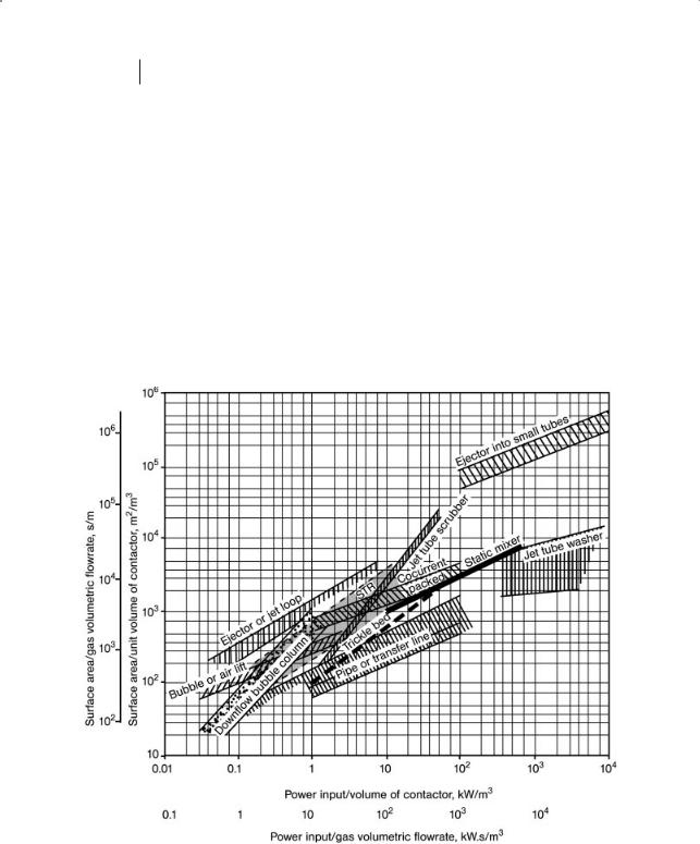
Table 1.1 summarizes such values. The values given are general; for specific applications they will differ. For example, the area/volume for bubble columns varies depending on the direction of flow. The relationship between the bubble area, bubble diameter, gas concentration in the liquid phase and the power input are given in Figs. 1.1 and 1.2.
Figure 1.1 Surface area versus power input for gas–liquid contactors.

Table 1.1 Some characteristics of GL contactors.
|
Gas vel. |
k ; mol/s |
k , mm/s |
k |
L |
a, 1/s |
a, m2/m3 |
L holdup |
Bulk/ |
Sh |
OTR |
|
|
|
|
G |
L |
|
|
|
|
|
|
|
|
|
|
|
m/s |
m2 MPa |
|
|
|
|
|
(1–e ) |
film vol. |
|
|
|
|
|
|
(mm/s) |
|
|
|
|
|
|
ratio, d+ |
|
|
|
|
|
|
|
|
|
|
|
|
|
|
|
g O2 |
mol O2 |
g O2 |
|
|
|
|
|
|
|
|
|
|
|
s–1 kW–1 |
s–1 m–3 |
s–1 m–3 |
Pipe contactor, |
0.01–0.5 |
5–80 |
0.2–0.5 |
0.02–1 |
50–2000 |
0.05–0.95 |
|
|
|
|
0.28 |
||
gas injection into |
|
|
|
|
|
|
|
|
|
|
|
|
|
liquid flowing in |
|
|
|
|
|
|
|
|
|
|
|
|
|
tube; vertical |
|
|
|
|
|
|
|
|
|
|
|
|
|
tube. |
|
|
|
|
|
|
|
|
|
|
|
|
|
Pipe contactor, |
|
5–40 |
0.1–1 |
0.005–0.7 |
50–700 |
0.05–0.95 |
|
|
|
|
|
||
horizontal and |
|
|
|
|
|
|
|
|
|
|
|
|
|
coiled tube |
|
|
|
|
|
|
|
|
|
|
|
|
|
Pipe contactor, |
|
|
|
|
|
|
40000– |
|
|
|
|
|
|
gas into liquid via |
|
|
|
|
|
|
500000 |
|
|
|
|
|
|
ejector into a tube |
|
|
|
|
|
|
|
|
|
|
|
|
|
Static mixer |
1–2 |
|
|
0.1–3 |
1000– |
|
|
|
0.9 |
|
|
||
in tube |
|
|
|
|
|
|
7000 |
|
|
|
|
|
|
Bubble column, |
0.01–0.3 |
5–20 |
0.1–0.6 |
0.005– |
20–1000 |
0.6–0.98 |
4000–104 |
400–1000 |
0.2–0.66 |
0.03– |
[0.9–1.3] |
||
with gas sparged |
|
(10–50) |
|
0.25 |
but |
|
|
(103 –104) |
|
0.045 |
|
||
at bottom; |
|
|
|
(0.05– |
usually |
|
|
|
|
|
|
||
counter current. |
|
|
|
0.15) |
50–700 |
|
|
|
|
|
|
||
H/D i 10 |
|
|
|
|
|
|
|
|
|
|
|
|
|
Bubble column, |
|
|
|
|
|
|
50–400 |
|
|
|
|
|
|
cocurrent. |
|
|
|
|
|
|
|
|
|
|
|
|
|
H/D i 10 |
|
|
|
|
|
|
|
|
|
|
|
|
|
Bubble column, |
|
|
|
0.0008 |
|
|
|
|
0.45 |
|
|
||
with gas diffuser |
|
|
|
|
|
|
|
|
|
|
|
|
|
at bottom; H/D i 10
13 contacting Phase Heterogenous Process: Chemical a for Context the about Thumb of Rules 6.1

Table 1.1 Continued.
|
Gas vel. |
k ; mol/s |
k , mm/s |
k |
L |
a, 1/s |
a, m2/m3 |
L holdup |
Bulk/ |
Sh |
OTR |
|
|
|
|
G |
L |
|
|
|
|
|
|
|
|
|
|
|
m/s |
m2 MPa |
|
|
|
|
|
(1–e ) |
film vol. |
|
|
|
|
|
|
(mm/s) |
|
|
|
|
|
|
ratio, d+ |
|
|
|
|
|
|
|
|
|
|
|
|
|
|
|
g O2 |
mol O2 |
g O2 |
|
|
|
|
|
|
|
|
|
|
|
s–1 kW–1 |
s–1 m–3 |
s–1 m–3 |
Bubble column, |
|
|
|
0.005– |
|
|
|
|
0.2–0.66 |
0.06–0.12 |
1.6–3.3 |
||
with diffuser |
|
|
|
0.08 |
200–600 |
|
|
|
[0.95] |
|
[2.5–2.9] |
||
plus turbine |
|
|
|
|
|
|
|
|
|
|
|
|
|
H/D i 10 |
|
|
|
|
|
|
|
|
|
|
|
|
|
Bubble column, |
0.01–0.2 |
5–20 |
0.1–0.4 |
0.005– |
100–300 |
0.5–0.7 |
|
|
|
|
|
||
packed[a] |
|
|
|
0.12 |
|
|
|
|
|
|
|
||
Bubble column, |
0.2–0.8 |
|
|
0.05–0.15 |
300–1000 |
0.7 |
|
|
0.3–1.2 |
0.03–0.3 |
2.8 [3.3] |
||
air lift, internal |
|
|
|
|
|
|
|
|
|
|
|
|
|
loop |
|
|
|
|
|
|
|
|
|
|
|
|
|
Bubble column, |
|
|
|
0.01–0.06 |
|
|
|
|
|
|
|
||
air lift, external |
|
|
|
|
|
|
|
|
|
|
|
|
|
loop |
|
|
|
|
|
|
|
|
|
|
|
|
|
Bubble column, |
|
|
0.4 |
0.2–1.2 |
200–5000 |
0.7 |
|
|
0.5–1.7 |
0.08–0.1 |
2.8 |
||
air lift, via jet |
|
|
|
|
|
|
usually |
|
|
|
[0.55] |
|
[2.5–3.2] |
loop (jet nozzle |
|
|
|
|
|
|
1000– |
|
|
|
|
|
|
reactor) |
|
|
|
|
|
|
2000 |
|
|
|
|
|
|
Spray, gravity |
0.5–3 |
5–20 |
0.07–0.15 |
0.0007– |
10–150 |
0.05; |
2–10 |
10–25 |
|
|
|
||
|
|
(10–50) |
|
0.015 |
|
0.02–0.2 |
|
|
|
|
|
||
Spray, Venturi |
0.7–1 |
(10–30) |
0.7 |
|
|
|
1000– |
I 0.3 |
|
|
|
|
|
scrubber |
|
|
|
|
|
|
7000 |
|
|
|
|
|
|
Spray, plunging |
|
|
|
0.2–1.2 |
|
|
|
|
0.25–0.9 |
|
3.3 |
||
jet |
|
|
|
|
|
|
|
|
|
|
[1.3] |
|
|
Spray, circulating |
|
|
|
|
|
|
|
|
|
|
0.6 [0.14] |
|
0.8 |
nozzle loop |
|
|
|
|
|
|
|
|
|
|
|
|
|
|
|
|
|
|
|
|
|
|
|
|
|
|
|
Thumb of Rules 1 14

Table 1.1 |
Continued. |
|
|
|
|
|
|
|
|
|
|
|
|
|
|
|
|
|
|
|
|
|
|
|
|
|
|
|
|
|
|
Gas vel. |
k ; mol/s |
k , mm/s |
k |
L |
a, 1/s |
a, m2/m3 |
L holdup |
Bulk/ |
Sh |
OTR |
|
|
|
|
|
G |
L |
|
|
|
|
|
|
|
|
|
|
|
|
m/s |
m2 MPa |
|
|
|
|
|
(1–e ) |
film vol. |
|
|
|
|
|
|
|
(mm/s) |
|
|
|
|
|
|
ratio, d+ |
|
|
|
|
|
|
|
|
|
|
|
|
|
|
|
|
g O2 |
mol O2 |
g O2 |
|
|
|
|
|
|
|
|
|
|
|
|
s–1 kW–1 |
s–1 m–3 |
s–1 m–3 |
Tray column, |
0.5–3 |
|
0.10–0.40 |
|
|
|
100–200 |
0.15–0.7 |
40–100 |
200–600 |
|
|
|
|
without down- |
|
|
|
|
|
|
|
|
|
|
|
|
|
|
comers |
|
|
|
|
|
|
|
|
|
|
|
|
|
|
Tray column, |
0.3–2.5 |
5–60 |
0.10–0.50 |
0.01–0.4 |
75–500; |
0.15–0.7 |
|
|
1–1.1 |
|
2.8 |
|||
sieve, with down- |
|
(20–200) |
|
|
|
|
usually |
|
|
|
[0.92] |
|
|
|
comers |
|
|
|
|
|
|
|
100–200 |
|
|
|
|
|
|
Tray column, |
|
5–20 |
0.1–0.5 |
0.01–0.2 |
100–400 |
0.1–0.95 |
|
|
|
|
|
|||
bubble cap, with |
|
|
|
|
|
|
|
|
|
|
|
|
|
|
downcomers |
|
|
|
|
|
|
|
|
|
|
|
|
|
|
Packed[a] |
column, |
1–2.2 |
0.3–20 |
0.06–0.2 |
0.0004– |
20–350 |
0.05–0.15 |
10–100 |
10–100 |
[0.27] |
|
0.14 |
||
random, counter- |
|
(10–50) |
|
0.07 |
|
|
(10–40) |
|
|
|
|
|||
current |
|
|
|
|
(0.01–0.8) |
|
|
|
|
|
|
|
||
Packed column, |
|
1–30 |
0.04–0.6 |
0.0004–1 |
400–3000 |
0.02–0.95 |
|
|
|
|
|
|||
cocurrent |
|
|
|
|
|
|
|
|
|
|
|
|
|
|
Packed, trickling |
|
|
|
|
|
|
45–115 |
|
|
|
|
|
|
|
filter |
|
|
|
|
|
|
|
|
|
|
|
|
|
|
Packed, struc- |
|
|
|
|
|
|
100–300 |
0.02 |
|
|
|
|
|
|
tured |
|
|
|
|
|
|
|
|
|
|
|
|
|
|
Thin film, gravity |
2 |
|
0.04–0.12 |
|
|
|
3–100 |
0.01–0.15 |
10–200 |
10–50 |
0.55 |
[0.025] |
0.8 |
|
Thin film, trickle |
i 0.01 |
|
|
|
|
|
100–3500 |
0.05–0.25 |
|
|
|
|
|
|
bed |
|
|
|
|
|
|
|
|
|
|
|
|
|
|
STR, gas sparged |
0.001– |
(10–50) |
0.03–0.5 |
0.003–0.8 |
50–4000 |
0.2–0.95 |
150–800 |
100–500 |
0.3–0.66 |
0.06–0.12 |
1.6–3.3 |
|||
into stirred tank |
0.02 |
|
|
(0.05–0.2) |
usually |
usually |
(103 –104) |
|
[1.5] |
[0.03–0.1] |
[2.5–2.9] |
|||
|
|
|
|
|
|
|
|
300–600 |
i0.7 |
|
|
|
|
|
|
|
|
|
|
|
|
|
|
|
|
|
|
|
|
15 contacting Phase Heterogenous Process: Chemical a for Context the about Thumb of Rules 6.1

Table 1.1 Continued.
Gas vel. |
k ; mol/s |
k , mm/s |
k |
L |
a, 1/s a, m2/m3 |
L holdup |
Bulk/ |
Sh |
OTR |
|
G |
L |
|
|
|
|
|
|
|
m/s |
m2 MPa |
|
|
|
|
(1– ) |
film vol. |
|
|
|
(mm/s) |
|
|
|
|
|
ratio, d+ |
|
|
|
|
|
|
|
|
|
|
|
g O2 |
|
|
|
|
|
|
|
|
|
s–1 kW–1 |
mol O2 |
g O2 |
s–1 m–3 |
s–1 m–3 |
STR, tubular |
|
|
impeller |
0.4 |
|
STR, turbine |
0.55–0.7 |
|
STR, propeller |
0.2–0.3 |
|
STR, gassing |
[0.7] |
4.1 |
tube |
|
|
[a] Characteristics of packing are given in Table 1.2.
Thumb of Rules 1 16
1.6 Rules of Thumb about the Context for a Chemical Process: Heterogenous Phase contacting 17
Table 1.2 Illustrative characteristics of packing.
|
|
a, m2/m3 |
Void volume for gas, e |
|
|
|
|
Structured packing |
|
100–300; usually 250 |
0.98 |
Raschig ring |
ceramic |
190–770 |
0.62–0.68 |
|
metal |
370 |
0.9 |
Saddle |
ceramic |
250–540 |
0.65–0.72 |
|
plastic |
80–120 |
0.9 |
Ring, slotted |
ceramic |
50–260 |
0.78–0.85 |
|
metal |
90–350 |
0.9–0.95 |
Tellerette |
|
190 |
0.93 |
Intallox |
|
120–620 |
0.78–0.8 |
Uniform spheres |
|
depends on size |
0.33–0.4 |
|
|
|
|
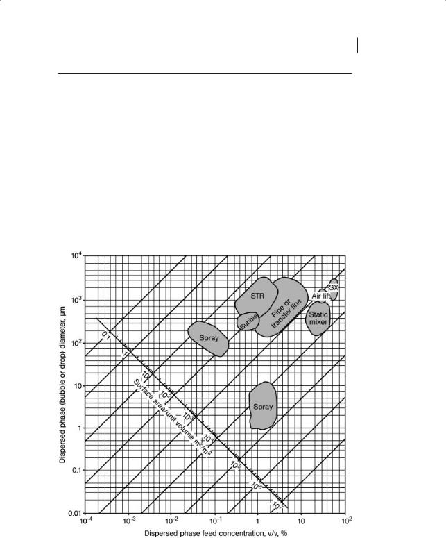
Figure 1.2 Surface area per unit volume for dispersed systems.

18 1 Rules of Thumb
Figure 1.1 shows the surface area generated as a function of power input per unit volume of “contactor” for a number of different GL contactors. Also shown in Fig. 1.1 is the surface area/gas volumetric flowrate as a function of the power per gas volumetric flowrate. Thus, the lowest values for an ejector or jet loop column correspond to a, the surface area/gas volumetric flowrate, = 1000 s/m and a power per gas volumetric flowrate = 1 kW s/m3.
1.6.2
LL Systems
LL contactors are used for direct contact heat exchange, Section 3.6; for solvent extraction, Section 4.10; for a wide variety of reactors; and for mixing, size decrease and size increase. For such contactors it is useful to know the following:
1.flow characteristics of the continuous and discontinuous phases: plug flow PF versus mixed flow MF or partial mixed flow PMF.
2.the residence time of the continuous phase.
3.the mass transfer coefficients.
4.holdup of the dispersed phase.
Table 1.3 summarizes this information.
Figure 1.2 shows the surface area as a function of the diameter of the dispersed phase bubbles, drops or particles and concentration. Also shown are illustrative regions for different contexts.
1.6.3
GLS Systems
For gas–liquid plus solids systems, the solids could be solid catalyst, inert solid or microorganisms. Most of the GL contacting systems given in Table 1.2 and Fig. 1.1 can handle the additional solid (although for Fig. 1.1, for GLS systems where a solid is suspended, about the same power input is needed for STR and cocurrent packed columns but about 1.2 to 2 times the power input is needed for suspension bubble columns). For GLS systems, additional contacting devices include fluidization, trickle beds and monolithic contactors. The diameter of catalytic or inert solid is usually about 1–200 mm. The amount of particulate catalyst or microorganisms in a reactor is 0.001–0.01 m3 catalyst/m3 reactor volume. For catalytic systems, the mass transfer coefficient across the liquid film to the solid, kLa, is as follows: bubble contactors: 0.25 1/s; jet loop and plunging jet: 0.1–1 1/s; trickling filter 0.06 l/s; sparged STR and fluidized bed: 0.1–0.5 1/s1.
For GLS systems for bioapplications, the solid is a microorganism. Some conditions are given in Table 6.9. The biofilm areas for fluidized and trickle beds are 2000m2/m3 vessel and 200m2/m3 vessel, respectively.

Table 1.3 Characteristics of LL contactors.
|
Continuous |
Disconti- |
Residence |
Superficial velocity, mm/s |
k , mm/s |
a, m2/m3 |
Dispersed |
Power input, |
|
|
|
|
|
|
|
L |
|
|
kW/m3 |
|
phase |
nuous phase |
time of |
|
|
|
|
phase hold- |
|
|
|
|
continuous |
|
|
|
|
up |
|
|
|
|
phase |
|
|
|
|
|
|
|
|
|
|
dispersed |
both |
|
|
|
|
|
|
|
|
|
|
|
|
|
|
Static mixer |
PF |
PF |
limited |
|
|
0.001–0.10 |
100–20000 |
0.05–0.2 |
|
Spray column, |
MF |
|
limited |
3–8 |
|
0.001–0.10 |
7–75 |
0.05–0.1 |
|
gravity |
|
|
|
|
|
|
|
|
|
Gravity RTL |
|
|
|
|
0.3–0.55 |
0.01–0.02 |
|
|
|
Karr pulsed column; |
|
|
|
|
8–11 |
0.01–0.02 |
|
|
|
reciprocating plate |
|
|
|
|
|
|
|
|
|
Tray, sieve column |
|
|
|
|
7.5–16 |
0.01–0.02 |
|
|
|
Tray, pulsed sieve |
|
|
|
2–20 |
3–4 |
0.01–0.02 |
75–3000 |
|
|
Packed, random |
PF |
PF |
limited |
1–20 |
3–8 |
0.001–0.025 |
7–75 |
0.05–0.1 |
|
Packed pulsed |
|
|
|
|
3–4 |
0.01–0.02 |
|
|
|
Stagewise packed |
|
|
|
|
3–4 |
0.01–0.02 |
|
|
|
with stirrer, |
|
|
|
|
|
|
|
|
|
Scheibel |
|
|
|
|
|
|
|
|
|
Thin film, gravity |
|
|
|
0.02–0.8 |
|
0.01–0.02 |
5–120 |
|
|
RDC |
|
|
|
|
4–8 |
0.01–0.02 |
|
|
|
STR with agitator |
MF |
PMF |
wide |
0.15–4 |
|
0.003–0.025 |
400–3500 |
0.01–0.5 |
0.2–3 |
|
|
|
variable |
|
|
|
|
|
|
Multistage STR |
|
|
|
2–20 |
|
0.001–0.01 |
100–2500 |
|
|
Inert gas agitation |
MF |
PMF |
wide |
|
|
0.001–0.003 |
1000–10000 |
0.05–0.3 |
|
|
|
|
variable |
|
|
|
|
|
|
|
|
|
|
|
|
|
|
|
|
19 contacting Phase Heterogenous Process: Chemical a for Context the about Thumb of Rules 6.1

201 Rules of Thumb
1.6.4
Particulate Systems
For particulate systems, the key characteristics are the surface area per unit volume (as shown in Fig. 1.2), the diameter of the particles (related to a commonly used method called Mesh size), the void volumes for a packed bed of particles and parameters to measure dry particle flowability.
Particle characterization includes measures of the size of particles and the flowability of dry powders. Size is frequently expressed as Mesh size (US Std is similar to Tyler). Mesh 325 = 44 mm; 270 = 53 mm; 230 = 63 mm; 200 = 74 mm; 170 = 88 mm; 140 = 105 mm; 120 = 125 mm; 100 = 149 mm; 80 = 177 mm; 70 = 240 mm; 60 = 250 mm; 50 = 297 mm; 40 = 420 mm; 30 = 590 mm; 20 = 840 mm; 18 = 1000 mm; 14 = 1410 mm; 12 = 1680 mm; 10 = 2000 mm; 8 = 2380 mm; 4 = 4760 mm.
Void volume between particles. For particulate systems it is useful to know the void space, or interstitial volume, e, in particulate systems. For a loose pack of uniform spheres, e = 0.45; for a tight pack of uniform spheres, e = 0.33; for fresh catalyst bed e = 0.42 decreasing to 0.38 as the bed ages; for uniform tower packing with sphericity of 0.4, e = 0.66. The void volume decreases as the particle distribution deviates from uniformity. For example, for a log normal distribution with a geometric standard deviation of 3, then for a tight pack of spheres e = 0.18.
For the flowability, use the Johanson indices to characterize dry particles: (see also related topics conveying solids, Section 2.6, storage bins, Section 10.3, mixing, Section 7.4) These indices are:
Arching index [m], AI, = diameter of the circular exit hole from a hopper that will ensure that an arch collapses in a conical bin or circular mixer, values range 0–1.2 m.
Ratholing index [m], RI, = diameter of the circular exit hole from a hopper that will ensure rathole failure and cleanout in a funnel-flow bin or mixer, values range from 0–9 m. (If RI i 3 then likely “lumps”.)
Hopper Index [degrees], HI = the recommended conical half-angle (measured from the vertical) to ensure flow at the walls. Usually add 3h to account for variability. Values range 14–33h with 304 s/s.
Flow ratio index [kg/s], FRI = maximum solids flowrate expected after deaearation of a powder in a bin. (Measures consistency: small FRI for fine, highly compressible particles; large FRI for particles i 400 mm, incompressible, very permeable.) Values range 0–90 kg/s.
Bin density index [Mg/m3], BDI = bulk specific mass expected in a container full of solids or, in a mixer, when mixer stops and solid is allowed to deaerate. Values 0.3–1.6 Mg/m3.
Feed density index [Mg/m3], FDI = bulk specific mass at the conical hopper or mixer’s discharge outlet. Values are 1–60 % I BDI.