

110 Kirilenko et al.
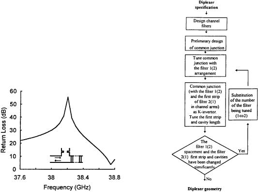
As shown in Figure 3, the next step in diplexer design is determining the locations of the channel filters with respect to the output ports of the common junctions. This is accomplished by satisfying eq. 3.. It appears that the variation in all three terms in eq. 3. has the same order of magnitude over the diplexer band. For example, let us consider the diplexer with the E-T common junction in Figure 1c with five pole channel filters. Our numerical calculations show that the main resonant term 2g l in eq. 3. changes by 2.48 within the passband 38.0]38.4 GHz. of the first filter. The phase of the reflection coefficient of the second filter varies by 6.08 within its passband38.8]39.2 GHz., while the phase of the third term decreases by 9.88 due to the dispersion of the S-matrix of the T-junction. Here the dispersion of S-matrix of the T-junction is compensated by the phase dispersion of the reflection coefficients of the channel filters. Consequently, the input matching is not unacceptably degraded. It is apparent from Figure 6 that the junction supposed to be matched by filter 2 reflects slightly within the passband of filter 1 and the corresponding passband ripple does not increase above 0.012 dB. The sharp increase of mismatch near the upper end of the band is due to the proximity of the passband of filter 2, where the second term in eq. 3. begins to increase quickly. It should be noted that the Y-scheme is applicable to diplexers having closely spaced channel filters, because the relatively narrow band matching centered around the center frequency fc j of the guard band may not cover the passbands of both filters if their center frequencies are widely separated. However, the configuration shown in Figure 4c is an exception. Its common junction characteristics al-
lows one to design diplexers with relatively large guard bands. The evolution strategy method w8x, however, also used two-step common junctions for numerical optimization of diplexers with geometries that are close to those discussed in this section.
VI. DESIGN PROCEDURE BASED ON TUNING THE LOADED COMMON JUNCTION AS A K-INVERTER
This design procedure is based on the method proposed in w9x and is further enhanced in this work. Here, each channel filter is designed under the assumption that the other filter and the common junction are integral parts of it. For instance, the first K-inverter of each filter is realized by three elements: the first discontinuity iris, septa, etc.., the common junction E-plane T-junction. and the reactance offered by the other filter at the center frequency of the filter being designed. Figure 7 shows the flow chart of the procedurewe call it the K-scheme.. First, the lumped element K-inverter circuits are found using conventional techniques w27, 28x. The filters are synthe-
Figure 6. Return loss of the E-T junction. |
Figure 7. Flow diagram of the K-scheme. |
CAD of Wa¨eguide E-Plane Diplexers 111
sized according to the flow chart in Figure 2. In the next step the influence of the other filter and the common junction on the value of the first K-inverter are taken into consideration. As a result, the length of the first septum is determined so that the load appearing at the boundary of the first resonator corresponds to the required value of the K-inverter. Since the phase of the load reflection coefficient seen from the first resonator has also changed, we always need to readjust the first resonator’s length. Obviously, such a design procedure is an iterative one because the adjustment of the first K-inverter in one filter affects that of the other filter and they load each other. This is indeed a very fast method because only distances among the pertinent discontinuities are varied and their S-matrices are calculated at two frequencies f01 and f02 .
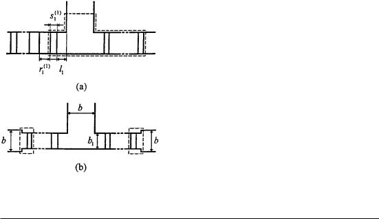
It is not mandatory in the K-scheme to use a three-port with certain specific features as is done in the Y-scheme. For example, let us consider the simplest diplexer design that uses the E-T as shown in Figure 8a. The dashed line marks the combined unit that plays the role of a K-inverter. The lengths of the strips s1 j., sections r1 j. and the distances lj , j s 1, 2, of the locations of the filters
Figure 8. E-plane T-junction common port.
from the common junction are the parameters for iterative tuning of the diplexer. Table I shows that the third iteration yields all dimensions with an accuracy better than that obtainable from manufacturing tolerances. Searching for the filter locations lj is used in the iteration scheme only for the preliminary tuning of the two-port formed by the three-port terminated at one of the ports by one of the filters as a plunger. However, some special configurations of the common junction allow one to design the diplexer without the filter placement tuning in the K-inverter scheme.
It is to be noted at this point that the K-inverter formed from a standard septum in rectangular waveguide and the K-inverter formed from more complex discontinuity in the K-inverter scheme have different frequency dependences. Therefore, it is necessary that the variations of K f . and arg K f . are not significantly different from that of the supposedly equivalent septum K-inverter within the passband of the filter. Figure 9 shows the results of frequency dispersion of the K-in- verter, shown by the dashed line in Figure 8a, over 0.2 GHz around 27.5 GHz. Figure 9 also shows the frequency dispersion of the corresponding septum K-inverter. The two dispersions curves compare very well and have very nearly similar characteristics. However, the arguments of two types of K-inverters vary by a factor of 1.5]2 between the band edges and the center frequencies of the channel filters. The dispersion of the arguments of the two types of K-inverters differ by not more than a factor of 1.5]2 within the passband see Figure 9b.. Similar small difference indispersion of combined K-inverters from separate strips allows us to obtain diplexer characteristics close to those of initially designed filters. The computer code for the K-scheme is more complex than that of the Y-scheme. However, the K-scheme does not require the expensive synthesis procedure for the common junction and it has no guard band limitation. K-scheme is applicable to both E- and H-plane common junction type diplexers w9x and also in unconventional configu-
TABLE I. Convergence of Iteration Procedure in K-Scheme for the simple E-T Diplexer Configuration
i |
l1 |
s11. |
r11. |
l2 |
s12. |
r12. |
1 |
6.838 |
0.4735 |
7.0703 |
5.371 |
0.6574 |
6.4936 |
2 |
6.677 |
0.4925 |
7.0528 |
5.589 |
0.6496 |
6.4923 |
3 |
6.668 |
0.4782 |
7.0662 |
5.588 |
0.6424 |
6.4843 |
4 |
6.668 |
0.4784 |
7.0660 |
5.588 |
0.6420 |
6.4833 |
5 |
6.668 |
0.4785 |
7.0660 |
5.588 |
0.6420 |
6.4833 |
|
|
|
|
|
|
|