

- •Textbook Series
- •Contents
- •1 Overview and Definitions
- •Overview
- •General Definitions
- •Glossary
- •List of Symbols
- •Greek Symbols
- •Others
- •Self-assessment Questions
- •Answers
- •2 The Atmosphere
- •Introduction
- •The Physical Properties of Air
- •Static Pressure
- •Temperature
- •Air Density
- •International Standard Atmosphere (ISA)
- •Dynamic Pressure
- •Key Facts
- •Measuring Dynamic Pressure
- •Relationships between Airspeeds
- •Airspeed
- •Errors and Corrections
- •V Speeds
- •Summary
- •Questions
- •Answers
- •3 Basic Aerodynamic Theory
- •The Principle of Continuity
- •Bernoulli’s Theorem
- •Streamlines and the Streamtube
- •Summary
- •Questions
- •Answers
- •4 Subsonic Airflow
- •Aerofoil Terminology
- •Basics about Airflow
- •Two Dimensional Airflow
- •Summary
- •Questions
- •Answers
- •5 Lift
- •Aerodynamic Force Coefficient
- •The Basic Lift Equation
- •Review:
- •The Lift Curve
- •Interpretation of the Lift Curve
- •Density Altitude
- •Aerofoil Section Lift Characteristics
- •Introduction to Drag Characteristics
- •Lift/Drag Ratio
- •Effect of Aircraft Weight on Minimum Flight Speed
- •Condition of the Surface
- •Flight at High Lift Conditions
- •Three Dimensional Airflow
- •Wing Terminology
- •Wing Tip Vortices
- •Wake Turbulence: (Ref: AIC P 072/2010)
- •Ground Effect
- •Conclusion
- •Summary
- •Answers from page 77
- •Answers from page 78
- •Questions
- •Answers
- •6 Drag
- •Introduction
- •Parasite Drag
- •Induced Drag
- •Methods of Reducing Induced Drag
- •Effect of Lift on Parasite Drag
- •Aeroplane Total Drag
- •The Effect of Aircraft Gross Weight on Total Drag
- •The Effect of Altitude on Total Drag
- •The Effect of Configuration on Total Drag
- •Speed Stability
- •Power Required (Introduction)
- •Summary
- •Questions
- •Annex C
- •Answers
- •7 Stalling
- •Introduction
- •Cause of the Stall
- •The Lift Curve
- •Stall Recovery
- •Aircraft Behaviour Close to the Stall
- •Use of Flight Controls Close to the Stall
- •Stall Recognition
- •Stall Speed
- •Stall Warning
- •Artificial Stall Warning Devices
- •Basic Stall Requirements (EASA and FAR)
- •Wing Design Characteristics
- •The Effect of Aerofoil Section
- •The Effect of Wing Planform
- •Key Facts 1
- •Super Stall (Deep Stall)
- •Factors that Affect Stall Speed
- •1g Stall Speed
- •Effect of Weight Change on Stall Speed
- •Composition and Resolution of Forces
- •Using Trigonometry to Resolve Forces
- •Lift Increase in a Level Turn
- •Effect of Load Factor on Stall Speed
- •Effect of High Lift Devices on Stall Speed
- •Effect of CG Position on Stall Speed
- •Effect of Landing Gear on the Stall Speed
- •Effect of Engine Power on Stall Speed
- •Effect of Mach Number (Compressibility) on Stall Speed
- •Effect of Wing Contamination on Stall Speed
- •Warning to the Pilot of Icing-induced Stalls
- •Stabilizer Stall Due to Ice
- •Effect of Heavy Rain on Stall Speed
- •Stall and Recovery Characteristics of Canards
- •Spinning
- •Primary Causes of a Spin
- •Phases of a Spin
- •The Effect of Mass and Balance on Spins
- •Spin Recovery
- •Special Phenomena of Stall
- •High Speed Buffet (Shock Stall)
- •Answers to Questions on Page 173
- •Key Facts 2
- •Questions
- •Key Facts 1 (Completed)
- •Key Facts 2 (Completed)
- •Answers
- •8 High Lift Devices
- •Purpose of High Lift Devices
- •Take-off and Landing Speeds
- •Augmentation
- •Flaps
- •Trailing Edge Flaps
- •Plain Flap
- •Split Flap
- •Slotted and Multiple Slotted Flaps
- •The Fowler Flap
- •Comparison of Trailing Edge Flaps
- •and Stalling Angle
- •Drag
- •Lift / Drag Ratio
- •Pitching Moment
- •Centre of Pressure Movement
- •Change of Downwash
- •Overall Pitch Change
- •Aircraft Attitude with Flaps Lowered
- •Leading Edge High Lift Devices
- •Leading Edge Flaps
- •Effect of Leading Edge Flaps on Lift
- •Leading Edge Slots
- •Leading Edge Slat
- •Automatic Slots
- •Disadvantages of the Slot
- •Drag and Pitching Moment of Leading Edge Devices
- •Trailing Edge Plus Leading Edge Devices
- •Sequence of Operation
- •Asymmetry of High Lift Devices
- •Flap Load Relief System
- •Choice of Flap Setting for Take-off, Climb and Landing
- •Management of High Lift Devices
- •Flap Extension Prior to Landing
- •Questions
- •Annexes
- •Answers
- •9 Airframe Contamination
- •Introduction
- •Types of Contamination
- •Effect of Frost and Ice on the Aircraft
- •Effect on Instruments
- •Effect on Controls
- •Water Contamination
- •Airframe Aging
- •Questions
- •Answers
- •10 Stability and Control
- •Introduction
- •Static Stability
- •Aeroplane Reference Axes
- •Static Longitudinal Stability
- •Neutral Point
- •Static Margin
- •Trim and Controllability
- •Key Facts 1
- •Graphic Presentation of Static Longitudinal Stability
- •Contribution of the Component Surfaces
- •Power-off Stability
- •Effect of CG Position
- •Power Effects
- •High Lift Devices
- •Control Force Stability
- •Manoeuvre Stability
- •Stick Force Per ‘g’
- •Tailoring Control Forces
- •Longitudinal Control
- •Manoeuvring Control Requirement
- •Take-off Control Requirement
- •Landing Control Requirement
- •Dynamic Stability
- •Longitudinal Dynamic Stability
- •Long Period Oscillation (Phugoid)
- •Short Period Oscillation
- •Directional Stability and Control
- •Sideslip Angle
- •Static Directional Stability
- •Contribution of the Aeroplane Components.
- •Lateral Stability and Control
- •Static Lateral Stability
- •Contribution of the Aeroplane Components
- •Lateral Dynamic Effects
- •Spiral Divergence
- •Dutch Roll
- •Pilot Induced Oscillation (PIO)
- •High Mach Numbers
- •Mach Trim
- •Key Facts 2
- •Summary
- •Questions
- •Key Facts 1 (Completed)
- •Key Facts 2 (Completed)
- •Answers
- •11 Controls
- •Introduction
- •Hinge Moments
- •Control Balancing
- •Mass Balance
- •Longitudinal Control
- •Lateral Control
- •Speed Brakes
- •Directional Control
- •Secondary Effects of Controls
- •Trimming
- •Questions
- •Answers
- •12 Flight Mechanics
- •Introduction
- •Straight Horizontal Steady Flight
- •Tailplane and Elevator
- •Balance of Forces
- •Straight Steady Climb
- •Climb Angle
- •Effect of Weight, Altitude and Temperature.
- •Power-on Descent
- •Emergency Descent
- •Glide
- •Rate of Descent in the Glide
- •Turning
- •Flight with Asymmetric Thrust
- •Summary of Minimum Control Speeds
- •Questions
- •Answers
- •13 High Speed Flight
- •Introduction
- •Speed of Sound
- •Mach Number
- •Effect on Mach Number of Climbing at a Constant IAS
- •Variation of TAS with Altitude at a Constant Mach Number
- •Influence of Temperature on Mach Number at a Constant Flight Level and IAS
- •Subdivisions of Aerodynamic Flow
- •Propagation of Pressure Waves
- •Normal Shock Waves
- •Critical Mach Number
- •Pressure Distribution at Transonic Mach Numbers
- •Properties of a Normal Shock Wave
- •Oblique Shock Waves
- •Effects of Shock Wave Formation
- •Buffet
- •Factors Which Affect the Buffet Boundaries
- •The Buffet Margin
- •Use of the Buffet Onset Chart
- •Delaying or Reducing the Effects of Compressibility
- •Aerodynamic Heating
- •Mach Angle
- •Mach Cone
- •Area (Zone) of Influence
- •Bow Wave
- •Expansion Waves
- •Sonic Bang
- •Methods of Improving Control at Transonic Speeds
- •Questions
- •Answers
- •14 Limitations
- •Operating Limit Speeds
- •Loads and Safety Factors
- •Loads on the Structure
- •Load Factor
- •Boundary
- •Design Manoeuvring Speed, V
- •Effect of Altitude on V
- •Effect of Aircraft Weight on V
- •Design Cruising Speed V
- •Design Dive Speed V
- •Negative Load Factors
- •The Negative Stall
- •Manoeuvre Boundaries
- •Operational Speed Limits
- •Gust Loads
- •Effect of a Vertical Gust on the Load Factor
- •Effect of the Gust on Stalling
- •Operational Rough-air Speed (V
- •Landing Gear Speed Limitations
- •Flap Speed Limit
- •Aeroelasticity (Aeroelastic Coupling)
- •Flutter
- •Control Surface Flutter
- •Aileron Reversal
- •Questions
- •Answers
- •15 Windshear
- •Introduction (Ref: AIC 84/2008)
- •Microburst
- •Windshear Encounter during Approach
- •Effects of Windshear
- •“Typical” Recovery from Windshear
- •Windshear Reporting
- •Visual Clues
- •Conclusions
- •Questions
- •Answers
- •16 Propellers
- •Introduction
- •Definitions
- •Aerodynamic Forces on the Propeller
- •Thrust
- •Centrifugal Twisting Moment (CTM)
- •Propeller Efficiency
- •Variable Pitch Propellers
- •Power Absorption
- •Moments and Forces Generated by a Propeller
- •Effect of Atmospheric Conditions
- •Questions
- •Answers
- •17 Revision Questions
- •Questions
- •Answers
- •Explanations to Specimen Questions
- •Specimen Examination Paper
- •Answers to Specimen Exam Paper
- •Explanations to Specimen Exam Paper
- •18 Index

Flight Mechanics 12
Emergency Descent
In the event of cabin pressurization failure at high altitude it is necessary to descend as quickly as possible. The rate of descent can be increased by:
•Reducing Thrust by closing the throttles.
•Increasing Drag by:
•extending the speedbrakes,
•lowering the landing gear (at or below VLO).
•Increasing speed by lowering the nose. Speed can be increased in the clean configuration
up to MMO or VMO depending on the altitude, or to the gear extended limit speed (VLE) if the gear is down.
The overall rate of descent will be higher with the landing gear extended (lots of Drag), but if the gear operating limit speed (VLO) is much less than the cruising speed, the aircraft will have to be slowed down before the gear can be lowered (perhaps taking several minutes in level flight). So the initial rate of descent will be relatively low and the time spent at high altitude will be extended.
If the gear is not extended, throttles can be closed, speedbrakes extended and the nose lowered to accelerate the aircraft to MMO/VMO immediately, giving a higher initial rate of descent and getting the passengers down to a lower altitude without delay.
At high altitude the limiting speed will be MMO, and if an emergency descent is made at this Mach number, the IAS will be increasing. At some altitude the IAS will reach VMO, and the nose must then be raised so as not to exceed VMO for the remainder of the descent.
The rate of descent possible during an emergency descent can be quite high, so as the required level-off altitude is approached, the rate of descent should be reduced progressively so as to give a smooth transition back to level flight.
Flight Mechanics 12
371
12 Flight Mechanics
Glide
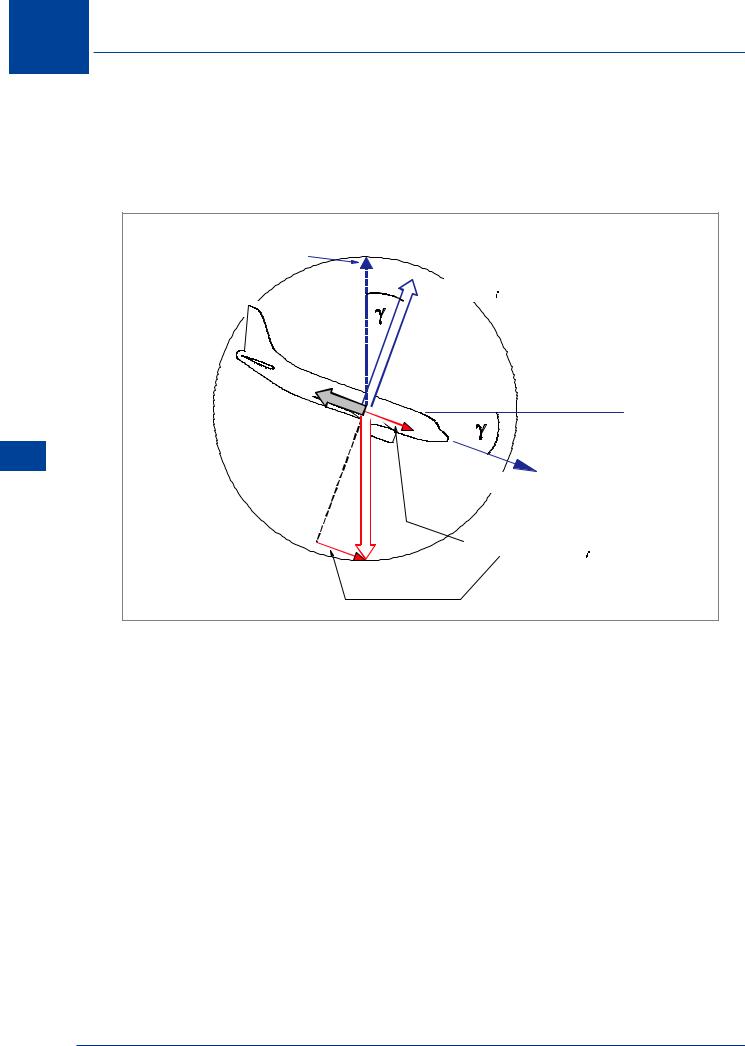
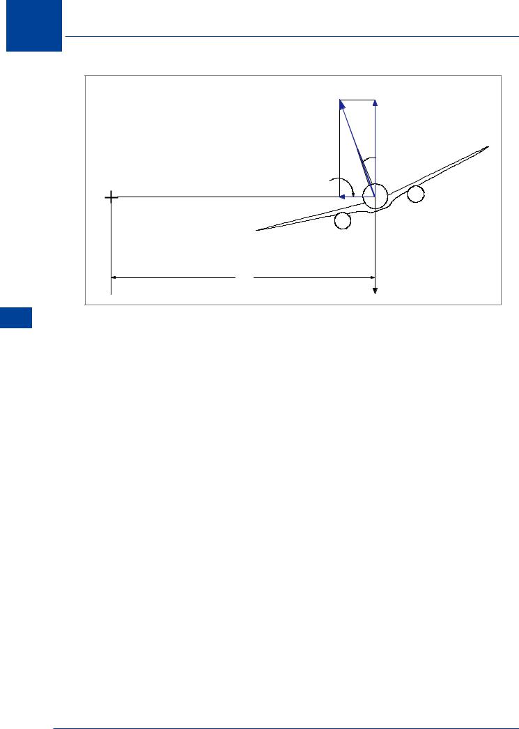
In a glide without Thrust, the Weight component along the flight path must supply the propulsive force and balance Drag. In a glide there are only three forces acting on the aircraft: Lift, Weight and Drag.
Mechanics Flight 12
TOTAL
REACTION
L= W cos 
D
FLIGHT PATH
FORWARD COMPONENT
OF WEIGHT ( W sin  )
)
W
Figure 12.8 Forces in the glide
Figure 12.8 shows the disposition of forces in a steady glide. The forward component of Weight (W sin γ) is a product of descent angle (γ); the greater the descent angle, the greater the forward component of weight (compare with Figure 12.7). The forward component of weight must balance Drag for the aircraft to be in a steady glide. It follows that if Drag is reduced and Lift remains constant, the required balance of forces can be achieved at a smaller descent angle.
Angle of Descent in the Glide
Glide angle is a function ONLY of the L/D ratio. The descent (glide) angle will be least when the L/D ratio is the greatest. L/D ratio is a maximum at the optimum angle of attack, and this also corresponds to the minimum drag speed (VMD), Figure 12.10. At speeds above or below VMD the glide angle will be steeper.
Maximum distance in a glide can be achieved when the aircraft is flown at L/D MAX (VMD).
372
Flight Mechanics
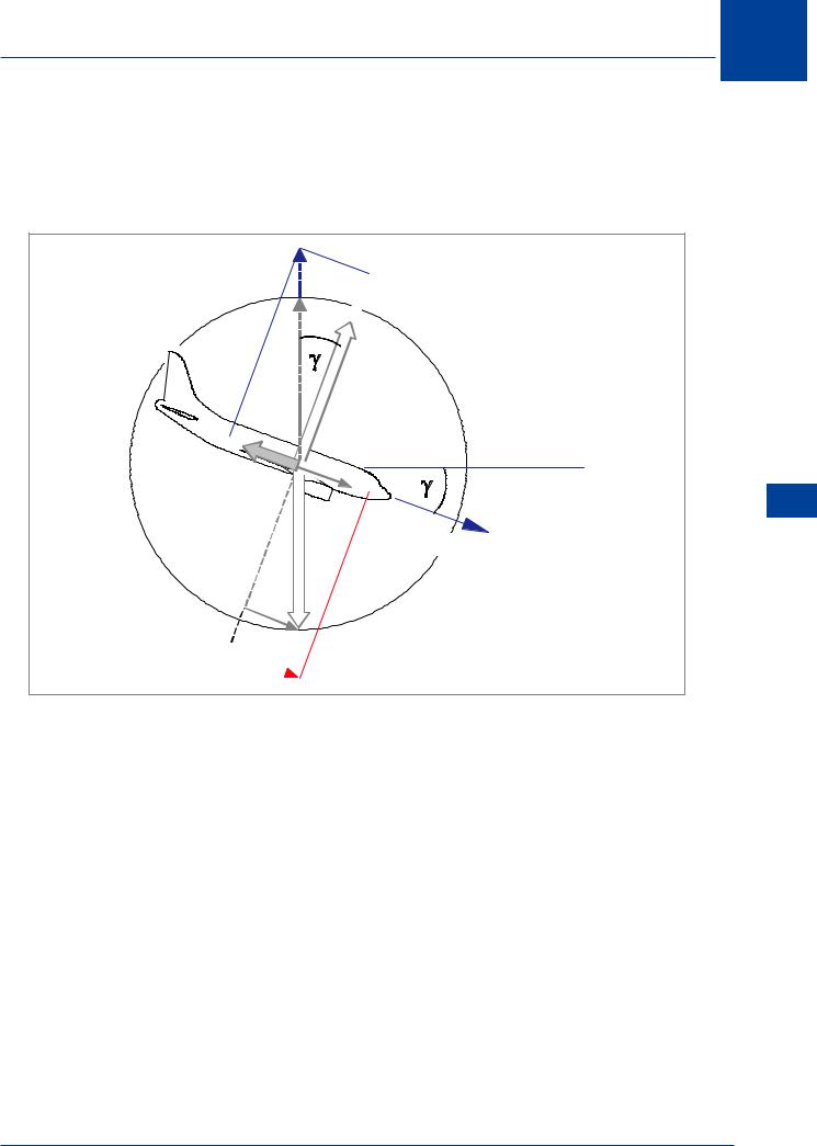
Effect ofWeight
L/D MAX is independent of weight. Provided the aircraft is flown at its optimum angle of attack, the glide angle and glide distance will be the same whatever the weight. The speed corresponding to the optimum angle of attack, (VMD), will, however, change with weight. VMD increases as weight increases.
 L
L
D
FLIGHT PATH

 W
W
Figure 12.9 Increased weight: no effect on glide range
As illustrated in Figure 12.9, a higher weight will give an increased forward component of weight and the aircraft will accelerate towards the resultant higher VMD. As the aircraft accelerates, lift increases and drag will increase until it balances the increased forward component of Weight. Equilibrium is now re-established at the same L/D MAX, but a higher IAS.
At a higher weight the aircraft will glide the same distance but at a higher speed, and consequently it will have an increased RATE of descent.
12
Flight Mechanics 12
373
12 Flight Mechanics
Effect ofWind
The glide angle will determine the distance that the aircraft can glide for a given change of height.
LIFT (L)
GLIDE DISTANCE = HEIGHT LOSS × DRAG (D)
Mechanics Flight 12
This distance would only be achieved in still air. If there is a wind, the ground speed will change, and so the distance over the ground will change. In a headwind the ground distance will be decreased, and in a tailwind it will be increased.
Effect of Configuration
The maximum L/D ratio of an aircraft will be obtained in the clean configuration. Extension of flaps, spoilers, speedbrakes or landing gear etc. will reduce L/D MAX and give a steeper glide angle, thus reducing glide range.
Rate of Descent in the Glide
Minimum rate of descent in the glide is obtained at the IAS which produces minimum Power Required (VMP). Flying at VMP in a glide will enable the aircraft to stay airborne for as long as possible. As shown in Figure 12.10, VMP is a slower IAS than VMD. Wind speed and direction has no effect on rate of descent. A frequently used method of showing the relationship of VMD and VMP is by use of the ‘whole aeroplane CL/CD polar’ curve, illustrated in Figure 12.11.
|
|
|
|
|
|
|
|
|
C L |
|
CLMAX |
|
|
|
|
|
|
|
|
|
|
|
|
|
|||
DRAG |
|
|
|
|
|
|
|
|
V MP |
|
|||
|
|
|
|
|
|
|
|
|
|
|
|
||
|
|
|
|
|
L / DMAX |
|
|
|
|
|
|
L/DMAX (VMD ) |
|
|
|
|
|
|
|
|
|
|
|
|
|
1.32V MD |
|
|
|
|
|
|
|
|
|
|
|
|
|
|
|
|
|
|
|
|
|
|
|
|
|
|
|
|
|
|
|
VMP VMD |
IAS |
|
|
|
|
|
C D |
|
|||
|
|
|
|
|
|
|
|
|
|
|
|
|
|
|
|
|
|
|
|
|
|
|
|
|
|||
|
|
Figure 12.10 |
|
|
|
|
|
|
Figure 12.11 |
|
|||
Turning
For an aircraft to change direction, a force is required to deflect it towards the centre of the turn. This is called the centripetal force, Figure 12.12. Banking the aircraft inclines the lift. It is the horizontal component of lift which causes the aircraft to turn. If the aircraft is banked and the angle of attack kept constant, the vertical component of lift will be too small to balance the weight and the aircraft will start to descend.
374
Flight Mechanics 12
As the angle of bank increases, the angle of attack must be increased to bring about a greater total lift. The vertical component must be large enough to maintain level flight, while the horizontal component is large enough to produce the required centripetal force.
Effect ofWeight onTurning
In a steady level turn, if thrust is ignored, lift provides a force to balance weight and centripetal force to turn the aircraft. If the same TAS and angle of bank can be obtained, the radius of turn is basically independent of weight or the aircraft type.
Not all aircraft can reach the same angle of bank at the same TAS. If weight increases, the vertical component of lift required increases, but the centripetal force to maintain the same radius of turn also increases in the same proportion. The lift required, although it is greater, has the same inclination to the vertical as before and the bank angle is the same, Figure 12.13.
Lift 
φ
CENTRIPETAL
FORCE
 Weight
Figure 12.12 Forces in a turn
Lift 
φ 
CENTRIPETAL
FORCE
Increased
Weight
Figure 12.13 Bank angle & weight
Flight Mechanics 12
375
12 Flight Mechanics
Mechanics Flight 12
|
|
L |
L cos φ |
CENTRE |
|
|
φ |
|
L sin φ |
|
|
OF TURN |
CENTRIPETAL FORCE |
|
|
|
r |
|
W |
|
|
|
Figure 12.14 Forces acting in a steady turn
In a steady horizontal turn, Figure 12.14, the conditions of equilibrium can be expressed in the form:
L cos φ = W |
(Eq 12.1) |
|
L sin φ = |
W V2 |
(Eq 12.2) |
|
r g |
|
where (L) is the wing lift in newtons, (W) is the weight of the aircraft in newtons, (V) the true airspeed in m/s, (r) the radius of turn in metres, φ the angle of bank and (g) the acceleration of gravity constant of 9.81 m/s2.
Dividing equation 2 by equation 1 we get:
tan φ = |
V2 |
(Eq 12.3) |
|
r g |
|||
|
|
which is the basic turning equation relating (V), (r) and φ. Once two of these variables are known, the other one can be determined. From equation 3, the radius of turn is given by:
Turn Radius = |
V2 |
|
g tan φ |
||
|
||
|
|
376

Flight Mechanics 12
and the corresponding rate of turn ( = V / r ) by:
Rate of Turn = |
g tan φ |
radians / second |
|
V |
|||
|
|
Rate of turn is the rate of change of heading or angular velocity of the turn. It may be expressed as degrees per minute, or by a Rate Number.
Rate 1 turn is 180° per minute (3° per second)
Rate 2 turn is 360° per minute (6° per second)
Rate of turn is directly proportional to TAS and inversely proportional to the turn radius.
Rate of Turn = |
TAS |
Radius |
|
|
|
For example: at a speed of 150 kt TAS (77 m/s), an aircraft performing a turn with a radius of 1480 metres would have a rate of turn of:
77 |
= 0.052 radians / sec |
|
|
|
1480 |
|
|
||
|
|
|
||
there being 2π radians in a circle, |
360 |
= 57.3° per radian |
||
6.286 |
||||
|
|
|
||
0.052 × 57.3 = 3° per second (Rate 1)
•At a constant TAS, increasing the angle of bank decreases the turn radius and increases the rate of turn.
•To maintain a constant rate of turn, increasing speed requires an increased bank angle.
•At a constant bank angle, increasing speed increases the turn radius and decreases the rate of turn.
In a Constant Rate Turn
The Angle of Bank is
Dependent Upon TAS
Flight Mechanics 12
377

12
Mechanics Flight 12
Flight Mechanics
Radius and Rate ofTurn
Two variables determine the rate of turn and radius of turn:
•Bank angle (φ). A steeper bank reduces turn radius and increases the rate of turn, but produces a higher load factor.
•True airspeed (TAS): Reducing speed reduces turn radius and increases the rate of turn, without increasing the load factor.
The radius of turn, at any given bank angle (φ), varies directly with the square of the TAS:
Radius = |
V2 |
|
g tan φ |
||
|
If speed is doubled, the turn radius will be four times greater, at a constant bank angle.
To appreciate the relationship between radius of turn and rate of turn at double the speed, consider:
Rate of Turn |
= |
|
V |
|
|
|
|
|
Radius |
|
|
||||
|
|
|
|
|
|||
Rate of Turn |
= |
|
V (×2) |
= |
1 |
||
Radius (×4) |
2 |
||||||
|
|
|
|||||
If speed is doubled, the rate of turn will be half of its previous value, at a constant bank angle.
Because the rate of turn varies with TAS at any given bank angle, slower aeroplanes require less time and area to complete a turn than faster aeroplanes with the same bank angle, Figure 12.15.
A specific angle of bank and TAS will produce the same rate and radius of turn regardless of weight, CG position, or aeroplane type. It can also be seen from Figure 12.15 that increasing speed increases the turn radius and decreases the rate of turn. The load factor remains the same because the bank angle has not changed.
To increase the rate and decrease the radius of turn, steepen the bank and/or decrease the speed.
A given TAS and bank angle will produce a specific rate and radius of turn in any aeroplane. In a co-ordinated level turn, an increase in airspeed will increase the radius and decrease the rate of turn. Load factor is directly related to bank angle, so the load factor for a given bank angle is the same at any speed.
378
Flight Mechanics 12
|
|
|
90 000 |
90 |
|
|
|
|
80 000 |
80 |
|
80º |
|
BANK |
70 000 |
70 |
|
|
60 000 |
60 |
|
||
|
ANGLE |
50 000 |
50 |
|
|
|
|
FOR |
40 000 |
40 |
|
|
|
RATE |
|
||
70º |
|
|
|
|
|
|
OF |
30 000 |
30 |
|
|
|
|
TURN |
|
|
|
60º |
|
20 000 |
20 |
|
|
50º |
|
|
|
|
|
|
40º |
|
|
|
|
|
30º |
10 000 |
10 |
|
|
|
9000 |
9 |
|
||
|
|
|
8000 |
8 |
|
|
|
20º |
7000 |
7 |
|
|
|
6000 |
6 |
|
|
|
|
|
|
||
|
|
|
5000 |
5 |
12 |
|
|
10º |
4000 |
4 |
MechanicsFlight |
|
|
|
3000 |
3 |
|
|
|
|
|
||
|
|
10º |
2000 |
2 |
|
20º |
|
|
|
||
|
|
|
|
||
30º |
|
1000 |
1.0 |
|
|
|
|
|
|
||
40º |
|
900 |
0.9 |
|
|
|
800 |
0.8 |
|
||
|
|
|
700 |
0.7 |
|
50º |
|
600 |
0.6 |
|
|
60º |
|
500 |
0.5 |
|
|
BANK ANGLE |
400 |
0.4 |
|
||
|
|
|
|||
70º |
|
FOR |
|
|
|
|
TURN RADIUS |
300 |
0.3 |
|
|
80º |
|
|
|||
|
|
|
|
||
|
|
|
200 |
0.2 |
|
TAS, |
Kts |
|
|
|
|
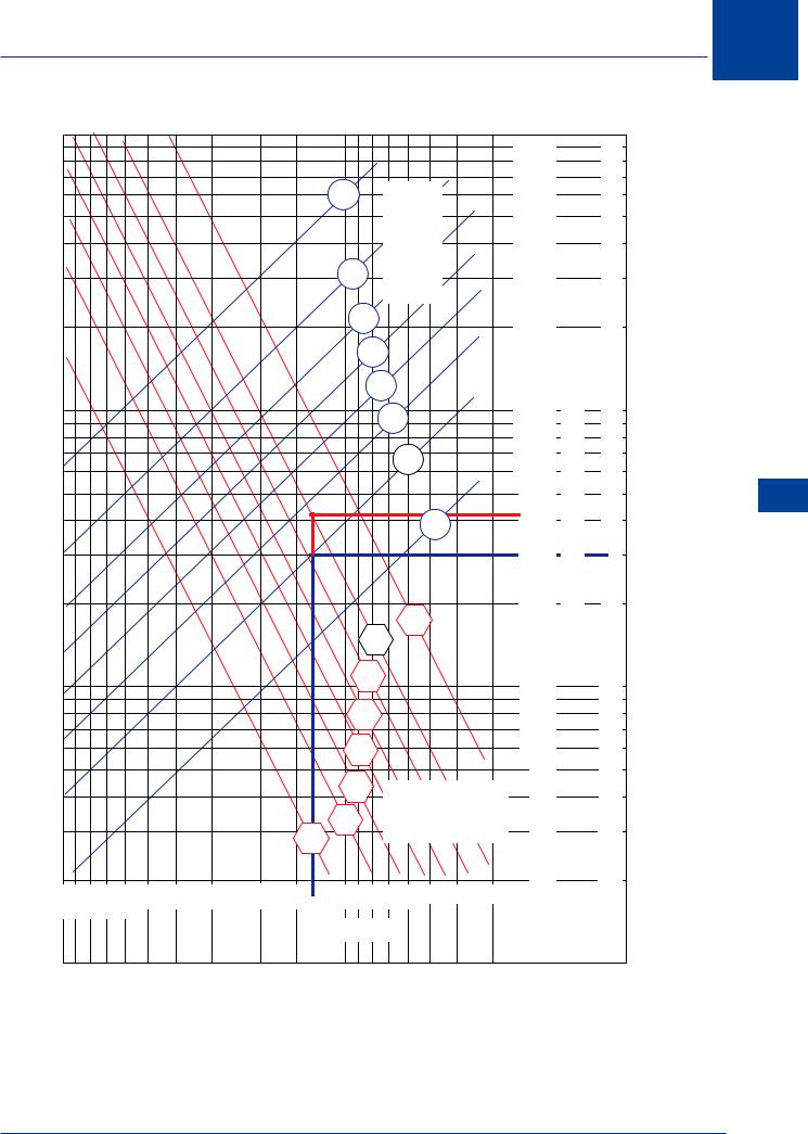
Figure 12.15
(For illustration purposes only). This chart will work for any aeroplane. The example shows that for a turn at 130 kt TAS and a bank angle of 20°, the radius will be 4200 ft and the rate of turn will be 3° per second. At 260 kt TAS the radius will be 16 800 ft and the rate of turn will be 1.5° per second.
379
12
Mechanics Flight 12
Flight Mechanics
Load Factor in theTurn
When an aircraft is in a banked turn, lift must be increased so as to maintain the vertical component of lift equal to weight, Figure 12.16.
|
INCREASED LIFT |
|
L |
|
|
CENTRIPETAL |
|
|
FORCE |
|
|
|
W |
|
60 |
BANK ANGLE |
30 BANK ANGLE |
Figure 12.16 Increased lift required in a turn
This relationship may be expressed as:
Load Factor (n) = |
L |
= |
1 |
= sec φ |
W |
cos φ |
Refer to Chapter 7 for the full trigonometrical explanation.
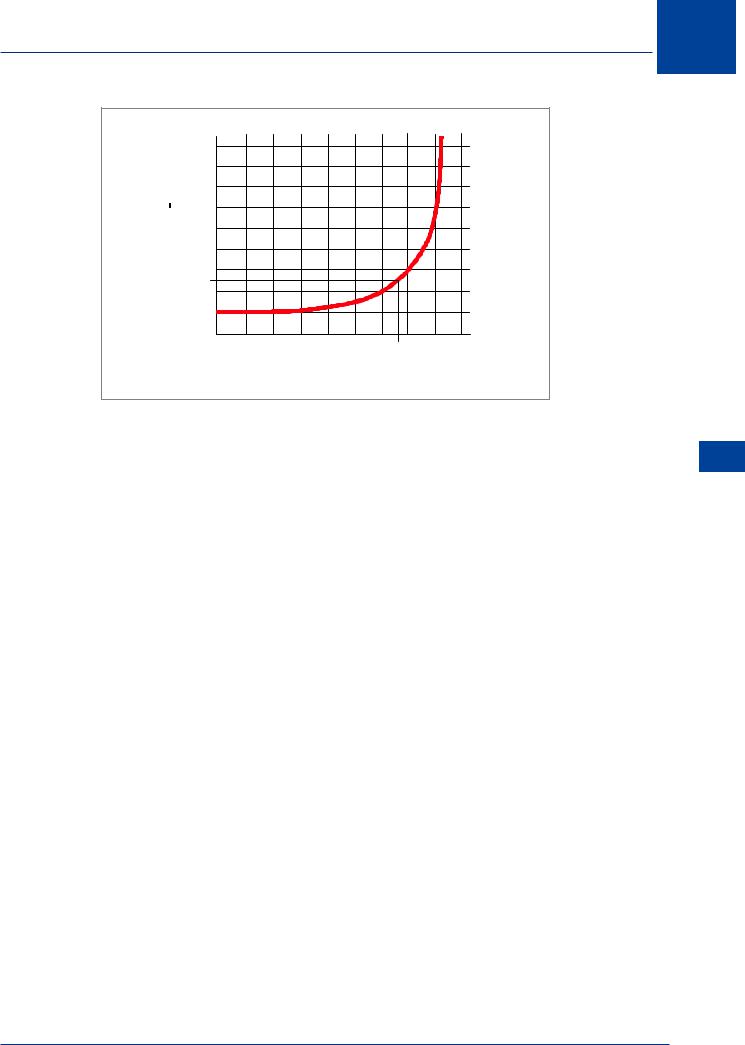
Figure 12.17 shows the relationship between load factor and bank angle. This chart will be effective for any aircraft. It can be seen that load factor (n) increases with bank angle at an increasing rate.
Load factor in the turn is a function ONLY of bank angle
Constant Bank Angle,
Constant Load Factor
380
Flight Mechanics 12
9 |
|
|
|
|
|
|
|
|
|
8 |
|
|
|
|
|
|
|
|
|
7 |
|
|
|
|
|
|
|
|
|
6 |
|
|
|
|
|
|
|
|
|
5 |
|
|
|
|
|
|
|
|
|
4 |
|
|
|
|
|
|
|
|
|
3 |
|
|
|
|
|
|
|
|
|
2 |
|
|
|
|
|
|
|
|
|
1 |
|
|
|
|
|
|
|
|
|
0 |
|
|
|
|
|
|
|
|
|
0 |
10 |
20 |
30 |
40 |
50 |
60 |
70 |
80 |
90 |
BANK ANGLE IN DEGREES
Figure 12.17 Relationship between ‘g’ & bank angle
‘g’ Limit onTurning
For each aircraft there is a design limit load factor. For modern high speed jet transport aircraft the positive limit load factor is 2.5g. From Figure 12.17 it can be seen that this would occur at a bank angle of 67°, and this will determine a turn radius, depending on the TAS. This will be the minimum radius permissible at that ‘g’ if the strength limit is not to be exceeded.
Stall Limit onTurning
If speed is kept constant, but the bank angle increased, the angle of attack must also be increased to provide the increased lift required. Eventually the stalling angle will be reached, and no further increase in bank angle (and decrease in turn radius) is possible. Because the stalling speed varies with weight, this boundary will be a function of weight.
Thrust Limit onTurning
During a turn lift must be greater than during level flight, and this will result in increased induced drag. To balance this additional drag, more thrust is required in a turn than for level flight at the same speed. The greater the bank angle, the greater will be the thrust required, and eventually the throttle will be fully open. No further increase in bank angle (and decrease in turn radius) is then possible. The relative positions of the thrust boundary and the strength boundary will depend on the limit load factor and thrust available.
MinimumTurn Radius
If the thrust available is adequate, the minimum radius of turn occurs at the intersection of the stall limit and the strength limit. The speed at this point is VA, the maximum manoeuvring speed. The heavier the aircraft, the greater the minimum radius of turn.
Flight Mechanics 12
381
12
Mechanics Flight 12
Flight Mechanics
Turn Co-ordination
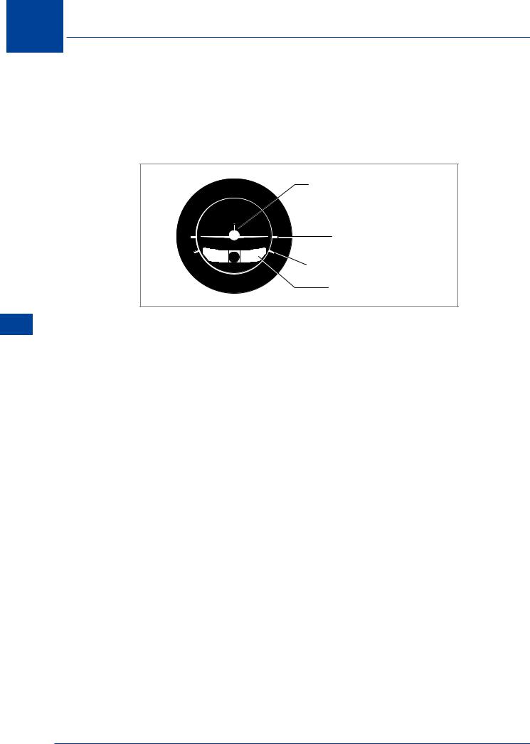
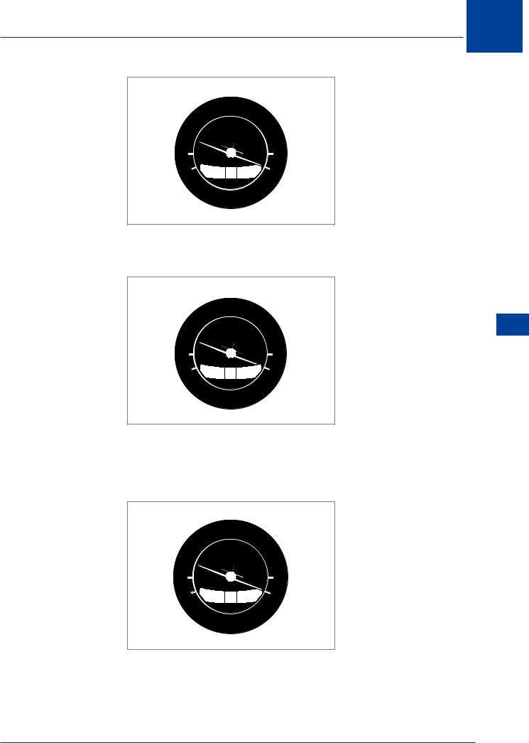
Adverse aileron yaw, engine torque, propeller gyroscopic precession, asymmetric thrust and spiral slipstream all give the possibility of unco-ordinated flight. Unco-ordinated flight exists when the aircraft is sideslipping. Indication of sideslip is given to the pilot by the inclinometer portion (ball) of the turn co-ordinator, Figure 12.18. The miniature aeroplane indicates rate of turn.
MINIATURE AEROPLANE
|
|
LEVEL INDEX |
L |
R |
RATE ONE TURN INDEX |
2 MIN |
|
|
|
|
INCLINOMETER |
Figure 12.18 Turn co-ordinator
Co-ordinated flight is maintained by keeping the ball centred between the reference lines with rudder. To do this, apply rudder pressure on the side where the ball is deflected. The simple rule, “step on the ball,” is a useful way to remember which rudder to apply.
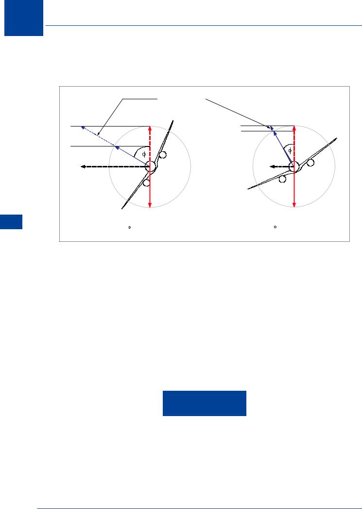
If aileron and rudder are co-ordinated during a turn, the ball will remain centred and there will be no sideslip. If the aircraft is sideslipping, the ball moves away from the centre of the tube. Sideslipping towards the centre of the turn moves the ball to the inside of the turn. Sideslipping towards the outside of the turn moves the ball to the outside of the turn. To correct for these conditions and maintain co-ordinated flight, “step on the ball.” Bank angle may also be varied to help restore co-ordinated flight from a sideslip. The following illustrations give examples.
382
Flight Mechanics 12
L  R
R
2 MIN
Figure 12.19
Figure 12.19 shows the aircraft in a rate 1 co-ordinated turn to the right.
L  R
R
2 MIN
Figure 12.20
Figure 12.20 shows the aircraft in an unco-ordinated turn to the right; it will be sideslipping towards the centre of the turn (slipping turn). Using “step on the ball,” the turn can be coordinated by applying right rudder pressure to centre the ball.
L  R
R
2 MIN
Figure 12.21
Figure 12.21 also shows the aircraft in an unco-ordinated turn to the right; it will be sideslipping towards the outside of the turn (skidding turn). Using “step on the ball,” the turn can be coordinated by applying left rudder pressure.
Flight Mechanics 12
383