


1108 |
CHAPTER 15. DIGITAL DATA ACQUISITION AND NETWORKS |
the master requests data and the slave replies. If we configure a process transmitter to burstcommunicate three di erent variables, for example, the update rate for each one of those variables will be approximately once per second (three variables communicated at a total rate of three HART telegrams per second), which is simply too slow for many industrial applications (e.g. closed-loop liquid flow control). In applications where speed is not a concern, however, HART communication is a very practical solution for acquiring multiple channels of data from one instrument over a single pair of wires.
15.11Modbus
Developed by the Modicon company (the original manufacturer of the Programmable Logic Controller, or PLC ) in 1979 for use in its industrial control products, Modbus is a protocol designed specifically for exchanging process data between industrial control devices. The Modbus standard does not specify any details of physical networking, and thus may be deployed on many di erent types of physical networks. In other words, Modbus primarily falls within layer 7 of the OSI Reference Model (the so-called “Application Layer”) and therefore is compatible77 with any lower-level communication protocols including EIA/TIA-232, EIA/TIA-485, Ethernet (the latter via TCP/IP), and a special token-passing network also developed by Modicon called Modbus Plus. The Modbus standard primarily defines the meaning of various Modbus commands, the addressing scheme used to place data within devices, and the formatting of the data.
Modbus consists of a set of standardized digital codes intended to read data from and write data to industrial devices. A Modbus-compliant industrial device has been programmed to understand these codes and respond to them appropriately when received. The simplest Modbus codes read and write single bits of data in the device’s memory, for example the status of a PLC input channel, PLC output channel, or status bit within a PLC program. Other Modbus codes operate on 16-bit words of data, useful for reading and writing counter and timer accumulated values, operands for mathematical instructions, converted analog signals, etc.
Early implementations of Modbus used EIA/TIA-485 as the network physical layer, which is strictly a layer 1 protocol. This meant that Modbus needed to specify a channel arbitration scheme in order to negotiate communications with multiple devices on a network. The arbitration chosen was master/slave, where one PLC functioned as the master Modbus device and all other devices functioned as Modbus slaves.
Interestingly, this vestige of master/slave arbitration survives to this day, even when Modbus commands are communicated via networks with their own di ering arbitration methods. For example, Modbus commands communicated over Ethernet still reference “slave” addresses even though the Ethernet network those messages are sent over uses CSMA/CD arbitration. In other words, there is a hint of OSI layer 2 embedded within Modbus messages that still dictates which Modbus devices may issue commands and which must obey commands.
77These Modbus data frames may be communicated directly in serial form, or “wrapped” in TCP segments and IP packets and Ethernet frames, or otherwise contained in any form of packet-based protocol as needed to transport the data from one device to another. Thus, Modbus does not “care” how the data is communicated, just what the data means for the end-device.
15.11. MODBUS |
1109 |
15.11.1Modbus overview
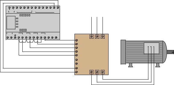
We may begin our exploration of Modbus by first considering an example of a PLC-controlled motor system that does not employ Modbus. Here, the PLC sends individually-wired Forward, Reverse, and Stop, and speed-control command signals to a variable-frequency drive (VFD) which then sends three-phase power of varying frequency to an electric motor to do some useful task:
|
24V |
DC |
I/0 |
I/1 |
I/2 |
I/3 DC |
|
I/4 |
I/5 |
Analog |
To 480 VAC |
|
||
|
|
COM |
|
|
|
COM |
|
|
output |
3-phase |
|
|
||
|
DC OUT |
|
|
|
|
|
|
|
|
|
|
|
||
|
|
|
|
|
|
|
|
|
|
|
power source |
|
||
|
|
Power |
|
|
|
|
|
|
|
|
|
|
|
|
|
|
Run |
|
|
|
|
PLC |
|
|
|
|
|
||
|
|
Fault |
|
|
|
|
|
|
|
|
|
|||
|
|
Force |
|
|
|
|
|
|
|
|
|
|
|
|
85-264 VAC |
|
|
|
|
|
|
|
|
Modbus |
|
|
|
|
|
L1 |
L2/N |
VAC |
O/0 |
VAC |
O/1 |
VAC |
O/2 |
VAC |
O/3 |
RS-485 |
|
|
|
|
VDC |
VDC |
VDC |
VDC |
|
|
|
|
|||||||
|
|
|
|
|
|
|
|
|
|
Stop |
L1 |
L2 |
L3 |
AC induction motor |
|
|
|
|
|
|
|
|
|
|
|
||||
|
|
|
|
|
|
|
|
|
|
Fwd |
|
|
|
|
|
|
|
|
|
|
|
|
|
|
Rvs |
|
|
|
|
|
|
|
|
|
|
|
|
|
|
Fwd jog |
|
VFD |
|
|
|
|
|
|
|
|
|
|
|
|
Com |
|
|
||
|
|
|
|
|
|
|
|
|
|
Modbus |
|
|
|
|
|
|
|
|
|
|
|
|
|
|
RS-485 |
|
|
|
|
|
|
|
|
|
|
|
|
|
|
Analog |
T1 |
T2 |
T3 |
|
|
|
|
|
|
|
|
|
|
|
speed |
|
|
|
|
|
|
|
|
|
|
|
|
|
|
command |
|
|
|
|
The discrete commands (e.g. Stop, Forward, Reverse) are nothing more than on/o contact closures provided by the PLC’s output channels to the VFD’s input terminals. When the PLC commands the VFD to run in the Reverse direction, it simply activates output channel O/1 which closes a relay contact inside the PLC to connect the VFD’s “Rvs” terminal to the VFD’s “Com” terminal. The VFD detects this electrical continuity, and responds by running the motor in its reverse direction. Motor speed is commanded by an analog voltage signal (typically 0 to 10 volts DC) output by the PLC, with 0 volts representing zero speed and 10 volts representing full speed. The VFD receives this analog voltage signal and responds to it by outputting the appropriate frequency of three-phase AC power to the induction motor.
While this system is certainly functional, it may be improved upon through the use of Modbus.
1110 |
CHAPTER 15. DIGITAL DATA ACQUISITION AND NETWORKS |
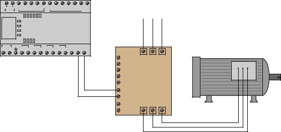
Now consider this updated motor control system, where the only connecting wires between the PLC and VFD is a single two-conductor cable between the Modbus/RS-485 terminals of both devices. The PLC functions as a Modbus master device while the VFD functions as a Modbus slave:
|
24V |
DC |
I/0 |
I/1 |
I/2 |
I/3 |
DC |
|
I/4 |
I/5 |
Analog |
|
|
|
COM |
|
|
|
|
COM |
|
|
output |
||
|
DC OUT |
|
|
|
|
|
|
|
|
|
|
|
|
|
Power |
|
|
|
|
|
|
|
|
||
|
|
Run |
|
|
|
|
|
PLC |
|
|||
|
|
Fault |
|
|
|
|
|
|
||||
|
|
Force |
|
|
|
|
|
|
|
|
||
85-264 VAC |
|
|
|
|
|
|
|
|
|
Modbus |
||
|
|
VAC |
|
VAC |
|
VAC |
|
VAC |
|
|||
L1 |
L2/N |
O/0 |
O/1 |
O/2 |
O/3 |
RS-485 |
||||||
VDC |
VDC |
VDC |
VDC |
|||||||||
To 480 VAC 3-phase power source
Stop |
L1 |
L2 |
L3 |
AC induction motor |
|
||||
Fwd |
|
|
|
|
Rvs |
|
|
|
|
Fwd jog |
|
VFD |
|
|
Com |
|
|
||
Modbus |
|
|
|
|
RS-485 |
|
|
|
|
Analog |
T1 |
T2 |
T3 |
|
speed |
|
|
|
|
command |
|
|
|
|
By using appropriate Modbus commands transmitted to the VFD, the PLC is able to issue all the same commands (e.g. Stop, Forward, Reverse, speed control) as before but using far fewer wires. For example Modbus command code 05 writes a single bit of data to the receiving device, allowing the PLC to send discrete-signal commands to the VFD one at a time. When the PLC commands the VFD to run in the Reverse direction, it issues a 05 command followed by a “1” data bit addressed to the appropriate memory location inside the VFD reserved for the “Reverse” command bit. When the PLC commands the VFD to change motor speed, it issues an 06 Modbus code (“write register”) followed by a 16-bit number representing the desired motor speed and the appropriate address within the VFD reserved for speed command.
Not only can the PLC issue all the same commands as before, but it may also read data from the VFD which it could not do before. For example, if the VFD provides a memory location for storing fault codes (e.g. motor overcurrent, bus undervoltage, etc.), the PLC may be programmed to issue an 03 Modbus code to read a single register (16 bit binary number) from that memory location within the VFD, and thereby monitor the status of the VFD to alert human technicians of potential problems, and/or to modify its own controlling of the motor.
15.11. MODBUS |
1111 |
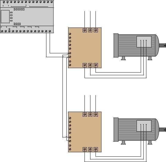
Another advantage of the Modbus communication standard is that it is designed to address multiple devices on the same network. This means our hypothetical PLC is not limited to controlling and monitoring just one motor, but up to 247 separate Modbus slave devices on the same two-wire communication cable! The following illustration shows how this might work for multiple motors:
|
24V |
DC |
I/0 |
I/1 |
I/2 |
I/3 DC |
|
I/4 |
I/5 |
Analog |
To 480 VAC |
|
||
|
|
COM |
|
|
|
COM |
|
|
output |
3-phase |
|
|
||
|
DC OUT |
|
|
|
|
|
|
|
|
|
|
|
||
|
|
|
|
|
|
|
|
|
|
|
power source |
|
||
|
|
Power |
|
|
|
|
|
|
|
|
|
|
|
|
|
|
Run |
|
|
|
|
PLC |
|
|
|
|
|
||
|
|
Fault |
|
|
|
|
|
|
|
|
|
|||
|
|
Force |
|
|
|
|
|
|
|
|
|
|
|
|
85-264 VAC |
|
|
|
|
|
|
|
|
Modbus |
|
|
|
|
|
L1 |
L2/N |
VAC |
O/0 |
VAC |
O/1 |
VAC |
O/2 |
VAC |
O/3 |
RS-485 |
|
|
|
|
VDC |
VDC |
VDC |
VDC |
|
|
|
|
|||||||
|
|
|
|
|
|
|
|
|
|
Stop |
L1 |
L2 |
L3 |
AC induction motor |
|
|
|
|
|
|
|
|
|
|
|
||||
|
|
|
|
|
|
|
|
|
|
Fwd |
|
|
|
|
|
|
|
|
|
|
|
|
|
|
Rvs |
|
|
|
|
|
|
|
|
|
|
|
|
|
|
Fwd jog |
|
VFD |
|
|
|
|
|
|
|
|
|
|
|
|
Com |
|
|
||
|
|
|
|
|
|
|
|
|
|
Modbus |
|
#1 |
|
|
|
|
|
|
|
|
|
|
|
|
RS-485 |
|
|
|
|
|
|
|
|
|
|
|
|
|
|
Analog |
T1 |
T2 |
T3 |
|
|
|
|
|
|
|
|
|
|
|
speed |
|
|
|
|
|
|
|
|
|
|
|
|
|
|
command |
|
|
|
|
To 480 VAC 3-phase power source
Stop |
L1 |
L2 |
L3 |
AC induction motor |
|
||||
Fwd |
|
|
|
|
Rvs |
|
|
|
|
Fwd jog |
|
VFD |
|
|
Com |
|
|
||
Modbus |
|
#2 |
|
|
RS-485 |
|
|
|
|
Analog |
T1 |
T2 |
T3 |
|
speed |
|
|
|
|
command |
|
|
|
|
Each VFD is given its own Modbus network slave address, so that the PLC is able to distinguish between the two drives when communicating on the same wire pair. Every Modbus code transmitted by the PLC contains this address as a single byte (8 bits) of data in order to make the receiving VFD aware that the code applies to it and not to any other Modbus device on the network. In
1112 |
CHAPTER 15. DIGITAL DATA ACQUISITION AND NETWORKS |
this example, we may wish to address VFD #1 with Modbus address 1, and VFD #2 with Modbus address 2. The Modbus standard provides a “broadcast address” of 0 which addresses all devices on the network simultaneously. For example, if the PLC needed to start all motors in the same direction at once, it could issue a Modbus code 05 (write a single bit) to the same address inside each VFD representing the command bit for the correct direction of motor rotation. So long as the VFDs are identically configured, the data will be received and interpreted by each VFD identically which will cause them to both start up in the same direction.
The only disadvantages to using Modbus as opposed to dedicated wires for each sensing and control function are speed and reliability. Modbus is necessarily slower than dedicated wire control because the PLC cannot simultaneously issue di erent commands on the network. For example, if the PLC needed to tell a VFD to begin turning its motor in the forward direction at 1050 RPM, the Modbus-based system would need to issue two separate Modbus codes whereas the individuallywired system could issue these commands all at once. This disadvantage, however, is hardly worth considering if the Modbus network communicates at reasonably high speed (thousands of bits per second). The disadvantage of reliability may be readily perceived if we consider how each system would respond to a wire fault (e.g. one wire coming loose and disconnected from a screw terminal). In the individually-wired system, one wire fault disables that one motor-control function but not necessarily any of the other functions. In the Modbus-based system, one wire fault disables everything because any Modbus communication requires full function of that two-conductor communication cable. The problem is even larger when multiple devices are controlled by the same Modbus cable: if a fault occurs between the controlling PLC and all the field devices, the PLC will lose control (and monitoring) for every one of those field devices! This is a factor worth considering when deciding whether or not to use any digital communication method for monitoring and control of multiple devices.
Modbus, especially when implemented over simple serial networks such as EIA/TIA-232 and EIA/TIA-485, is a rather primitive protocol. The seemingly arbitrary decimal codes used to issue commands and specify addresses is antiquated by modern standards. For better or for worse, though, a great many digital industrial devices “speak” Modbus, even if they are also capable of communicating via other network protocols. Using Modbus to communicate with modern control equipment is therefore an act of homage to 1970’s-era telecommunications: all participating devices in a Modbus network essentially behave the same as a 1970’s vintage Modicon PLC for the sake of exchanging information, even if their processing capabilities enable communications far more sophisticated than the Modbus protocol. A Modbus device querying another Modbus device does not “know” how modern or antiquated that other device is, because the basic Modbus standard has remained fixed for all this time.
The rest of this section explores details of the Modbus standard: its command vocabulary, addressing scheme, and some examples of read/write operations.