

16.2. H1 FF PHYSICAL LAYER |
1147 |
16.2.2Coupling devices
In order to simplify the task of connecting Fieldbus devices to such a network segment, multiple manufacturers sell coupling devices (often informally referred to as bricks) with quick-disconnect electrical fittings so the end-user does not have to build and commission junction boxes using standard terminal blocks. A photograph of a Turck brand Fieldbus coupling device appears here, showing multiple spur cables plugged into it:
Coupling devices are highly recommended for all industrial fieldbus systems, FF or otherwise. Not only do these devices provide a convenient means of forming highly reliable connections between field instruments and the trunk cable, but many of them are equipped with features such as shortcircuit protection (so that a shorted spur cable or field instrument does not cause the entire segment to stop communicating) and LED indication of spur status.
Cables connecting to a coupling device must be equipped with special plugs matching the sockets on the coupler. This presents a bit of a problem when attempting to pull such a cable through electrical conduit: the bulky plug requires either over-sized conduit to accommodate the plug’s width, or requires the plug be installed on the cable after pulling through the conduit. Both approaches are expensive, the first in terms of capital cost and the second in terms of installation labor. For this reason, many installers abandon electrical conduit altogether in favor of ITC (“Instrument Tray Cable”).

1148 |
CHAPTER 16. FOUNDATION FIELDBUS INSTRUMENTATION |
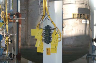
A wider-angle photograph of the coupling device previously shown reveals many ITC cables and their routing through wire “basket” style trays among process instruments and vessels:
As evident in this photograph, ITC is obviously rated for continuous exposure to direct sunlight and moisture, as well as a certain amount of physical distress (abrasion, high and low temperatures, etc.). Article 727 of the National Electrical Code (NEC) defines the acceptable uses and installations of ITC3.
It should be noted that while a properly shielded and grounded FF cable is quite resistant to radio-frequency interference, coupling devices may present “weak spots” where radio interference may find its way onto the segment. Di erent styles of coupling devices o er di ering levels of immunity to RF (Radio Frequency) noise. Those made of metal and properly bonded to ground will be well-shielded, while those made of plastic having exposed connection terminals o er little or no protection. In any case, it is a good practice to avoid “keying” any portable radio transmitter in the near vicinity of a Fieldbus coupling device.
3You should consult an NEC code book regarding specific limitations of ITC wiring. Some of the main points include limiting individual ITC cable lengths to a maximum of 50 feet, and mechanically securing the cable at intervals not to exceed 6 feet.
16.2. H1 FF PHYSICAL LAYER |
1149 |
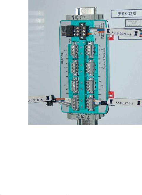
Not all Fieldbus couplers are rated for outdoor installation. Some are intended for mounting inside electrical enclosures, such as this Pepperl+Fuchs model shown mounted on a DIN rail:
This Fieldbus coupling device is aptly labeled a segment protector, for it not only couples spurs to the main trunk of the Fieldbus segment, but it also guards against short-circuits in the spur cables and devices from interrupting communication on the rest of the segment. If you look closely at the upper-left of the coupling device, you will see a black plastic square with two leads inserted into screw terminals: this is one of two terminating resistors found in this Fieldbus segment, meaning this particular coupling device is at the “end of the line” of the network segment.
Not only do enclosure-protected coupling devices eliminate the need for special weather-proof connectors and instrument tray cable, but they also enjoy the radio interference immunity4 granted by being inside a metal cocoon.
4Provided the metal enclosure’s door is left in the closed position at all times! Keying a radio transmitter near such a coupling device while the enclosure door is open invites trouble.
1150 |
CHAPTER 16. FOUNDATION FIELDBUS INSTRUMENTATION |
16.2.3Electrical parameters
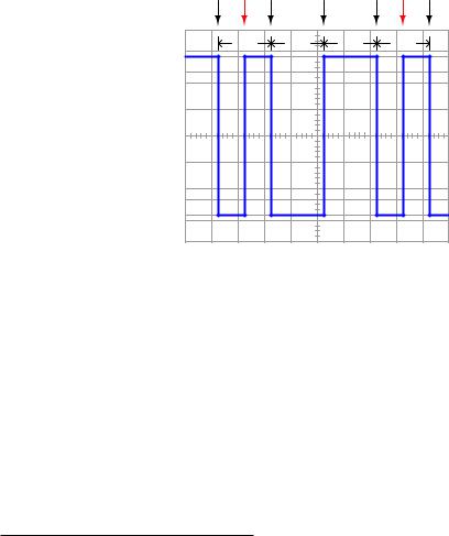
FOUNDATION Fieldbus H1 networks use Manchester encoding to represent bit states: a “high-to- low” transition represents a logical zero (0), while a “low-to-high” transition represents a logical one
(1). The following illustration shows how the data stream 00100 would be represented in Manchester encoding:
|
Manchester encoding |
|
|
|||
Clocked |
Reversal |
Clocked |
Clocked |
Clocked |
Reversal |
Clocked |
clock |
clock |
clock |
|
clock |
period |
period |
period |
|
period |
0 |
0 |
1 |
0 |
0 |
FF devices must be able to correctly distinguish between risingand fall-edge signals in order to properly interpret the bit states of a Manchester-encoded signal. Any device interpreting these pulse edges “backwards” will invert every single bit! Thankfully, this problem is easy to avoid because the DC power supplied by the H1 segment wiring provides a “key” to identifying which wire is which, and therefore which pulses are rising-edge versus which pulses are falling-edge. For this reason, many (but not all!) FF devices are polarity-insensitive, automatically detecting the polarity of the network segment and compensating accordingly.
Every FF device draws at least 10 mA of current from the segment, and this current does not vary in the same manner that an analog (4-20 mA) device draws di ering amounts of current under di erent operating conditions. Always remember that a Fieldbus device signals its variable(s) digitally, not by varying current. Old habits (and thought patterns) die hard, and so Fieldbus systems present challenges to technicians familiar with the behavior of analog current loop instrumentation. The amount of current drawn by any particular FF device depends on that device’s functionality – obviously, some will require more current5 for their operation than others. 10 mA to 30 mA should
5Perusing documentation on an assortment of Emerson/Rosemount FF products, I found the following data: model 752 indicator = 17.5 mA, model 848L logic = 22 mA, model 848T temperature = 22 mA maximum, model 3244MV temperature = 17.5 mA typical, model DVC6000f valve positioner = 18 mA maximum, model 848L logic = 22 mA,

16.2. H1 FF PHYSICAL LAYER |
1151 |
be considered a general range of current drawn by each FF device.
The standard operating voltage range for FF devices is between 9 and 32 volts DC. It is important to note, however, that not all manufacturers’ devices are in full compliance with the Fieldbus Foundation standard, and as such some may not operate properly at low voltages (near 9 volts DC)! The most common DC operating voltage for a FF network segment is 24 VDC (typical).
The minimum transmission voltage of a FF device is 750 millivolts peak-to-peak, while the minimum signal level for reception by a FF device is 150 millivolts peak-to-peak. This represents an acceptable attenuation of 5:1, or −14 dB between any two devices.
model 848T temperature = 22 mA maximum, model 3244MV temperature = 17.5 mA typical, model 5500 guidedwave radar level = 21 mA, model 3095MV flow (di erential pressure) = 17 mA approximate, model DVC6000f valve positioner = 18 mA maximum.