

discrete actuators - 5.1
5. LOGICAL ACTUATORS
Topics:
•Solenoids, valves and cylinders
•Hydraulics and pneumatics
•Other actuators
Objectives:
•Be aware of various actuators available.
5.1INTRODUCTION
Actuators Drive motions in mechanical systems. Most often this is by converting electrical energy into some form of mechanical motion.
5.2 SOLENOIDS
Solenoids are the most common actuator components. The basic principle of operation is there is a moving ferrous core (a piston) that will move inside wire coil as shown in Figure 5.1. Normally the piston is held outside the coil by a spring. When a voltage is applied to the coil and current flows, the coil builds up a magnetic field that attracts the piston and pulls it into the center of the coil. The piston can be used to supply a linear force. Well known applications of these include pneumatic values and car door openers.
current off |
current on |
Figure 5.1 |
A Solenoid |
discrete actuators - 5.2
As mentioned before, inductive devices can create voltage spikes and may need snubbers, although most industrial applications have low enough voltage and current ratings they can be connected directly to the PLC outputs. Most industrial solenoids will be powered by 24Vdc and draw a few hundred mA.
5.3 VALVES
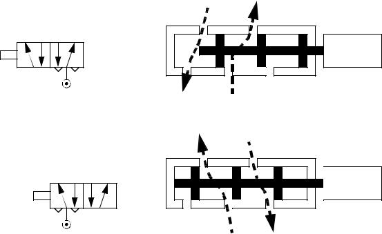
The flow of fluids and air can be controlled with solenoid controlled valves. An example of a solenoid controlled valve is shown in Figure 5.2. The solenoid is mounted on the side. When actuated it will drive the central spool left. The top of the valve body has two ports that will be connected to a device such as a hydraulic cylinder. The bottom of the valve body has a single pressure line in the center with two exhausts to the side. In the top drawing the power flows in through the center to the right hand cylinder port. The left hand cylinder port is allowed to exit through an exhaust port. In the bottom drawing the solenoid is in a new position and the pressure is now applied to the left hand port on the top, and the right hand port can exhaust. The symbols to the left of the figure show the schematic equivalent of the actual valve positions. Valves are also available that allow the valves to be blocked when unused.
The solenoid has two positions and when actuated will change the direction that fluid flows to the device. The symbols shown here are commonly used to represent this type of valve.
solenoid |
exhaust out power in
solenoid |
power in |
exhaust out |
Figure 5.2 A Solenoid Controlled 5 Ported, 4 Way 2 Position Valve
discrete actuators - 5.3
Valve types are listed below. In the standard terminology, the ’n-way’ designates the number of connections for inlets and outlets. In some cases there are redundant ports for exhausts. The normally open/closed designation indicates the valve condition when power is off. All of the valves listed are two position valve, but three position valves are also available.
2-way normally closed - these have one inlet, and one outlet. When unenergized, the valve is closed. When energized, the valve will open, allowing flow. These are used to permit flows.
2-way normally open - these have one inlet, and one outlet. When unenergized, the valve is open, allowing flow. When energized, the valve will close. These are used to stop flows. When system power is off, flow will be allowed.
3-way normally closed - these have inlet, outlet, and exhaust ports. When unenergized, the outlet port is connected to the exhaust port. When energized, the inlet is connected to the outlet port. These are used for single acting cylinders.
3-way normally open - these have inlet, outlet and exhaust ports. When unenergized, the inlet is connected to the outlet. Energizing the valve connects the outlet to the exhaust. These are used for single acting cylinders
3-way universal - these have three ports. One of the ports acts as an inlet or outlet, and is connected to one of the other two, when energized/unenergized. These can be used to divert flows, or select alternating sources.
4-way - These valves have four ports, two inlets and two outlets. Energizing the valve causes connection between the inlets and outlets to be reversed. These are used for double acting cylinders.
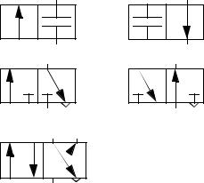
Some of the ISO symbols for valves are shown in Figure 5.3. When using the symbols in drawings the connections are shown for the unenergized state. The arrows show the flow paths in different positions. The small triangles indicate an exhaust port.
Two way, two position
normally closed |
normally open |
Three way, two position
normally closed |
normally open |
Four way, two position
discrete actuators - 5.4
Figure 5.3 ISO Valve Symbols
When selecting valves there are a number of details that should be considered, as listed below.
pipe size - inlets and outlets are typically threaded to accept NPT (national pipe thread).
flow rate - the maximum flow rate is often provided to hydraulic valves. operating pressure - a maximum operating pressure will be indicated. Some valves
will also require a minimum pressure to operate.
electrical - the solenoid coil will have a fixed supply voltage (AC or DC) and current.
response time - this is the time for the valve to fully open/close. Typical times for valves range from 5ms to 150ms.
enclosure - the housing for the valve will be rated as,
type 1 or 2 - for indoor use, requires protection against splashes type 3 - for outdoor use, will resists some dirt and weathering type 3R or 3S or 4 - water and dirt tight
type 4X - water and dirt tight, corrosion resistant
5.4 CYLINDERS
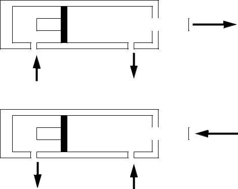
A cylinder uses pressurized fluid or air to create a linear force/motion as shown in Figure 5.4. In the figure a fluid is pumped into one side of the cylinder under pressure, causing that side of the cylinder to expand, and advancing the piston. The fluid on the other side of the piston must be allowed to escape freely - if the incompressible fluid was trapped the cylinder could not advance. The force the cylinder can exert is proportional to the cross sectional area of the cylinder.
discrete actuators - 5.5
F
advancing
Fluid pumped in |
Fluid flows out |
at pressure P |
at low pressure |
F
retracting
Fluid flows out |
|
Fluid pumped in |
at low pressure |
|
at pressure P |
For Force: |
|
|
P = |
F |
F = PA |
-- |
||
|
A |
|
where,
P = the pressure of the hydraulic fluid A = the area of the piston
F = the force available from the piston rod
Figure 5.4 A Cross Section of a Hydraulic Cylinder
Single acting cylinders apply force when extending and typically use a spring to retract the cylinder. Double acting cylinders apply force in both direction.