

книги / Innovative power engineering
..pdfAllhorizontaltraversesshouldbecoveredbyaerodynamic crosssection profilecovering;
Housing of alternator should have an oval shape;
Smoothing ofall prominent parts to reduce the ultrasound.
Fig. 6. Rotor and hub of WT-3
Component: Alternator (Fig. 7). The task is reduction of mass and cost price.
Fig. 7. Alternator of WT (chart, outside view, winding)
Possible ways and technologies to be used:
Lowspeedsynchronousaxialgap (valvular) alternator (expensive due to the high cost of magnets);
Asynchronizedsynchronous alternator;
Lowspeedsynchronousradialgapalternator;
Highspeedsynchronous(valvular)alternator with gearbox (planetary gear, eddy currents, etc.);
21
Improvealternator housing for better cooling and filtration of air pumping in.
Component: – Power controller of WT. The task is to improve a software. Possible ways and functional technologies to be used:
Systemofintellectualpowercontrol of WT;
System of charge-discharge of accumulating batteries;
Intellectual system of determination of local grid parameters;
System of stochastic analysis and prognosing.
Component: Power controller of hybrid wind-solar plant. The task is to improve a software. Possible ways and functional technologies to be used:
Systemofintellectualpowercontrol of WT;
Systemofintellectualpowercontrol of solar panel battery;
System of charge-discharge of accumulating batteries;
Intellectual system of determination of local grid parameters (optional);
System of stochastic analysis and prognosing (optional).
WT control theory
The power of wind flow passing trough the swept area of wind turbine, should be calculated as shown by formula (1):
P = 0,5 S V3,
where P – power (W); – air density (normal 1.23 kg/m3); S – rotorsweptarea (m2); V – windflowspeed (m/s).
The main aerodynamic curve: dependence of power coefficient Cp on tip speed ratio Z (ratio of linear blade speed to wind speed) for WT- 3(6) is shown on Fig. 8. Linear speed of the blade 2.1 times higher than the wind speed.
The main tsakofcontroliskeeping a maximal Cp value loading and unloading the alternator.
22
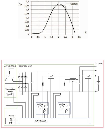
Fig. 8. Dependence of power coefficient Cp on tip speed ratio Z for WT-3(6)
The electric chart of WT-3(6) connections is shown in Fig. 9.
Fig. 9. WT connection chart, simplified
The chart of methodology of VAWT development is shown in Fig. 10. It demonstrates the optimizing of parts and ideas in the process of WT improvement and usage of new parts [7, 8].
23
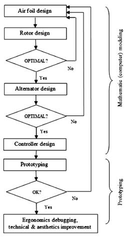
Fig. 10. Structure of VAWT component development
References
1.Solomin E.V. State of World Wind Industry Development //
Mezhdunarodnyj nauchnyj zhurnal «Al'ternativnaja energetika i ekologija». – Sarov, 2014 – 1 (1). – S. 22–26.
2.Gusev A.L., Solomin E.V. Vetroenergetika Kitaja (kratkij obzor) //
Mezhdunarodnyj nauchnyj zhurnal «Al'ternativnaja energetika i ekologija». – Sarov, 2014. – – S. 10–23.
24
3. Sostojanie razvitija mirovoj vetroindustrii / E.A. Sirotkin, E.V.
Solomin [i dr.] // Mezhdunarodnyj nauchnyj zhurnal «Al'ternativnaja energetika i ekologija». – Sarov, 2014. – – S. 20–25.
4.Avtonomnoe energosnabzhenie ob’ektov Krajnego Severa / N.A. Pavlov,
D.S. Rogachev, A.V. Sinickij, E.V. Solomin // Mezhdunarodnyj nauchnyj zhurnal «Al'ternativnaja energetika i ekologija». – Sarov, 2015. – 10(174). – S. 75–83.
DOI: 10.15518/isjaee.2015.10.007.
5.Tvajdel Dzh., Ujejr A. Vozobnovljaemye istochniki energii / per. s angl. pod red. V.A. Korobkova. – M: Energoatomizdat, 1990. – S. 195–242.
6.Sostojaniemalojvetrojenergetiki v mire / E.A. Sirotkin, E.V. Solomin
[i dr.] // Mezhdunarodnyj nauchnyj zhurnal «Al'ternativnaja energetika i ekologija». – Sarov, 2014. – – S. 26–31.
7.Solomin E.V. Iteratsionnaja optimizacija parametrov i rezhimov raboty vertikal'no-osevykh vetroenergeticheskikh ustanovok // Vestnik JuUrGU. Ser. «Energetika». – Cheljabinsk: Izd-vo JuUrGU, 2011. – Vyp. 15(232). – S. 73–81.
8.Solomin E.V. Metodologijarazrabotki i sozdanijavertikal'no-osevykh vetroenergeticheskikh ustanovok: monografija. – Cheljabinsk: Izd-vo JuUrGU, 2011. – 324 s.
25
RESEARCH ON EFFECTS OF FUEL PYROLYSIS TO PERFORMANCE OF INTERNAL COMBUSTION ENGINE
Zhenjian Jia1, Weixing Zhou2,*, Wenchao Liu1
1 School of Energy Science and Engineering, Harbin Institute of Technology, Harbin, Heilongjiang, 150001, P. R. China
2 Academy of Fundamental and Interdisciplinary Sciences, Harbin Institute of Technology, Harbin, Heilongjiang, 150001, P. R. China
A new power cycle is proposed for improving the efficiency of internal combustion engine (ICE), which is throughout regenerative cooling to enhance the heat value of fuel, then make the combustion condition in ICE better. The scheme is proved to be feasible by means of thermodynamic and combustion analysis. An experimental platform is built to conduct re-cooled experiment, the results demonstrate that fuel releases heat absorbed from cooling process in combustor can reduce the heat loss and fuel consumption of ICE effectively.
Keywords: Internal combustion engine (ICE), Regenerative cooling.
Introduction
There are low combustion efficiency and high pollutant emission problems with conventional internal combustion engines. For example, the combustion of gasoline engine (GE) is premixed homogeneous spark-ignited combustion (PHSIC) with low compression ratio and low thermal efficiency. While the combustion of conventional diesel engine (DE) is diffusive combustion, which means the fuel and air can’t mix sufficiently because of short mixing time. The combustion of DE is divided into high-temperature flame zone and high-temperature overthick zone. There is a great deal of soot and NOx in the exhaust. Generally, the exhaust of ICE has a high temperature from 400 °C to 700 °C, it consumes about 25 to 45 % heat of the calorific value of fuels. In that case, it’s a general measure to improve the cycle efficiency by utilize the waste heat fully and reasonably.
To solve the problem of low waste-heat utilization and difficult in improving the combustion efficiency of ICE, a new power cycle is proposed to improve the efficiency of ICE. This cycle can improve the
26
calorific value of fuel by regenerative cooling and make the combustion regime inside ICE better. Meanwhile, fuel releases the heat absorbed from cooling process in combustor, which can lower the heat loss and fuel consumption of ICE.
|
|
|
Table 1 |
|
Power utilization of ICE |
|
|
|
|
|
|
|
Effective work |
Exhaust |
Cooling process |
GE |
25–30 % |
26–35 % |
12–27 % |
DE |
30–40 % |
20–30 % |
15–35 % |
1. Theoretical verification
|
Waste-heat |
|
of exhaust |
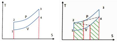
Fig. 1. Temperature-entropy |
Fig. 2. Temperature-entropy diagram |
diagram of Isobaric heating |
of Isobaric heating cycle of ICE |
cycle of ICE |
with regenerator |
The compression ratio ( ) of gasoline engine (GE) is within ±2 of 7, let us assume the compression ratio ( ) equals to 7, while the pressure rise ratio ( ) equals to 2.5, and the mechanical efficiency ( ) equals to 0.7. Because the combustion gases of GE is a mixture of multiple atomic, the isentropic exponent is from 1.32 to 1.18 generally, here we assume !0=1.35, heat recovery coefficient " = 1. Similarly, the compression ratio of diesel engine (DE) is from 13 to 20, assuming the compression ratio ( ) equals to 16, the pre-expansion ratio ( ) equals to 2.5, the mechanical efficiency ( ) equals to 0.7, heat recovery coefficient "=1. The isentropic exponent is within ±0.1 of 1.39 because
27
the combustion gases of DE is a mixture of multiple atomic. Hence, !0=1.39. The Reheating Regenerative Cycle increase the efficiency of GE and DE from 34.6%, 40.7% up to 42.4% and 45.4 respectively.
2. Confirmatory experiment
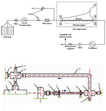
Pyrolysis experiment system is used to analysis the performance of fuel pyrolysis as sown in Figure 3.
Fig. 3. Experimental system of high temperature pyrolysis
1-Cylinder liner of ICE, 2-Nozzle, 3-Fuel injection pump, 4-Insulation device, 5-VDD, 6-Heating pipeline, 7-GND, 8,12-Four-way excuse, 9,13-Pressure sensor, 10,14-Temperature sensor, 11-Cooling pipeline,
Fig. 4. Schematic diagram of the ICE regenerative cooling experiment platform
The ICE regenerative cooling experiment platform is a confirmatory experimental system. In order to simulate the process of fuel endothermic, a means of electric heating is used and the fuel is sprayed into the combustor the spray nozzle as shown in Fig. 4.
28
3. Experimental results and discussion
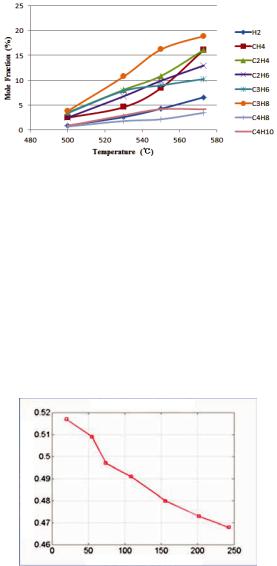
Fig. 5. Distribution of gaseous products
The content of CH4 and H2 increases with the temperature rise and smooth gradually in high-temperature zone. The co-combustion characteristics of H2 improve the combustion regime a lot. Second, hydrogen has strong catalysis to the carbon-oxygen reaction, which makes the combustion conduct more completely. Third, the small molecule hydrocarbons such as compounds of C2 and C4 remain high, which benefit the improvement of effect of the spray. Finally, there is less acetylene compounds in the gaseous products. The increase of acetylene compounds will lead to higher degree of unsaturation of hydrocarbon fuel and higher hydrogen content.
Fuel Consumption rate (Kg/Kw·h)
Fuel heating temperature (°C)
Fig. 6. Relationship between Fuel consumption rate and inlet temperature
29
The fuel consumption rate decreases with the temperature rise, which means the rise of fuel temperature enhance the thermal efficiency and the combustion efficiency of internal combustion engine (ICE), thus it proves that this system can decrease fuel consumption indeed.
Summary
In this work, a new power cycle is proposed for improving the efficiency of internal combustion engine (ICE), which is throughout regenerative cooling to enhance the heat value of fuel, then make the combustion condition in ICE better. We can learn by thermodynamic analysis that utilizing the waste-heat by regenerative cooling can improve the efficiency of ICE notably. Moreover, the combustion analysis indicates that the increase of gas molecules after pyrolysis can reduce exhausted pollutant heavily, which proves the feasibility of this scheme. Regenerative cooling experiment has been conducted on a selfbuilt experimental platform. The results indicate the process that fuel releases heat absorbed from cooling process in combustor can reduce the heat loss and fuel consumption of ICE effectively.
30