

книги / Innovative power engineering
..pdfFor the flowrate in each nozzle is quite low, a peristaltic pump (FB-RDB6) is employed to spray periodically under a range of 1.25 mL/min-650 mL/min, cf. Fig. 3.
Fig. 3. The diagram |
Fig. 4. The diagram of mini-type fan |
of peristaltic pump |
|
It’s difficulty to spray the cold water in single liquid phase due to ultralow flowrate and low pressure of peristaltic pump. Thus air assistant spray was taken into consideration. A min-type fan was set to blast air into the nozzle and thus crush the liquid film into fragments. A fan (WS7040-24-8) was selected, which provide a wind pressure as high as 6 kpa. Considering the pipe resistance, the final pressure was reduced to 3–4 kpa. Additionally, by slotting the cold water pipe inserted in the nozzle, a liquid film with 0.05 mm in thickness was obtained. Thereafter, air blasting happened to the thin film for better spray atomization. According to the force balance on the liquid film, the film would break up into pieces as external force overcomes the viscous force and surface tension, which is descripted as:
|
p , |
(11) |
|
air |
|
|
|
where Q is surface tension, R is the liquid film thickness, and pair is air pressure provided by fan. Then substitute the data into the equation as below:
61
|
0.0731 |
1462 pa 3000 pa. |
(12) |
|
|||
0.00005 |
|
||
A conclusion can be arrived that the spray is technically practical. Moreover, the spray atomization is implemented due to the variation of surface tension and aerodynamics. The spray mode can be classified as the first wind-induced spray. According to the theory, the droplets size is in the same magnitude of liquid jetting. Thus the droplet size is predicted as 0.05 mm as well.
2.2. The prototype of system
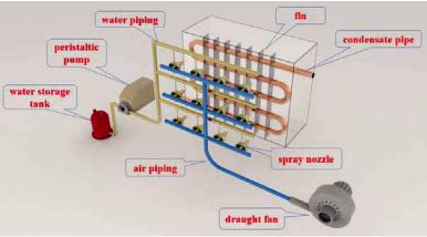
As shown in Fig. 5, a micro spray system based on condensate water, which contain water system and air system. Water storage tank, peristaltic pump and water pipe, all of them made up the water system. Water storage tank, cover with insulation layer that used for preventing condensate water exchange heat with the environment, is used to collect condensed water. Condensate via the water piping to spray nozzle by the driving of the pump; Air system include draught fan and air piping. The air outside is pump to the nozzle by the fan before mixed with condensate water, then mixture of air and condensed water would transfer heat with refrigerant of High temperature and high pressure through the fin.
Fig. 5. The overall system diagra006D
62
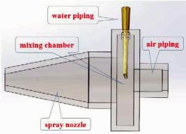
Key component of the system is spray nozzle, just as shown in Fig. 6. Condensate water is pumped into nozzle via the water piping, at the end of which is designed to be flat with fistulous internal structure, making condensate water well atomized and distributed in the mixing chamber. When air through the air piping to the chamber and crash the spray of condensate water into smaller droplets. It would improve the heat transfer coefficient and increase the refrigeration capacity under combined effect of the improving of air flow rate and the evaporation of the recycling condensate water, so as to achieve the effect of energy conservation and emissions reduction.
Fig. 6. Schematic diagram of spray nozzle
3. Efficiency calculation
The efficiency calculation of the system has been carried out, which is related to economy and reliance. For instance, the refrigerating capacity was set as 7200 W, power rating was set as 2410 W.
The operating condition were as following: outdoor environment temperature was 36.5 °C, the indoor temperature was controlled at 26 °C, condensation temperature was 50 °C, evaporation temperature was 5 °C, subcooling temperature drop was 5 °C, superheating temperature increase is 2 °C. The pressure drop and flash evaporation is neglected during the refrigerant flow process and the refrigerant working medium was assumed to be R22.
63
The refrigeration cycle of P-h was shown in Fig. 8. The calculated COP was as follows:
COP |
h2 h1 |
|
408.62 256.31 |
5.00. |
(13) |
h3 h2 |
|
||||
|
|
439.08 408.62 |
|
||
The flow rate of R22 was:
qm |
|
7200 |
|
47.27 g/s. |
(14) |
||
408.62 |
256.31 |
||||||
|
|
|
|
||||
As shown in Fig. 7. When spray wasn’t adopted, all the heat of condenser was used to heat air, on the enthalpy wet graph was a straight up line point 1 to point 2. It can be figured out:
Q G h2 h1 . |
(15) |
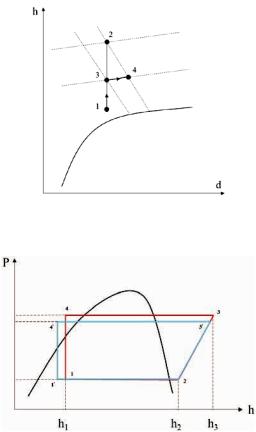
When spray was adopted, condenser heat dissipating capacity was divided into two parts: the evaporation latent heat of the condensate water Qwater, the heat used to heat the air Qair. The air in the condenser can be considered as a constant moisture content heating process, as shown in Fig. 8, point 1 to point 3, then the heated air absorbed the vapored condensate water at a constant temperature, the state of the mixed turned into point 4. The process on the psychrometric chart was point 3 to point 4. It can be figured out:
Q Qwater Qair , |
(16) |
Qwater Mwater hlatent , |
(17) |
Qair G h3 h1 kA t, |
(18) |
Qwater G h4 h3 . |
(19) |
In the aforementioned formulas, Q was total heat exchange amount; Qwater was heat exchange mount of condensate water; Qair was heat exchange mount of air; M was mass flow rate of condensate water; K was coefficient of heat transfer; A was heat transfer area of condenser. It can be concluded that the increase of Qwater give rise to the
64
decrease of Qair, when the heat exchange amount was constant. The heat exchange area and the coefficient of heat transfer remain unchanged, hence St decreased, result in the decreasing of condensing temperature. The calculating result showed that the condensing temperature decreased about 2.85 °C.
Fig. 7. Enthalpy wet figure of the heating processes of the cooling air
Fig. 8. Refrigeration cycle comparison before and after adding spray
As shown in Figure 8. The refrigerating cycle were 1-2-3-4 before spray system was added. The condensing temperature decreased after spray system was added, and the refrigerating cycle turned into 1’-2-3’-4’.
65
Checked the pressure-enthalpy chart of R22, it can be calculated as follows:
COP |
408.62 256.31 |
|
5.00, |
(20) |
|
|
|||||
1 |
439.08 |
408.62 |
|
|
|
|
|
|
|||
COP |
408.62 |
252.85 |
5.36. |
(21) |
|
|
|||
2 |
437.69 |
408.62 |
|
|
|
|
|||
The main calculation results were shown in Table 4:
|
|
|
|
Table 4 |
|
Systemic changes before and after adding spray |
|||
|
|
|
|
|
|
|
Refrigerating |
Compression work |
COP |
|
|
capacity (kJ/kg) |
(W) |
|
|
|
|
||
No spray |
|
7200 |
1439.84 |
5.00 |
Spray |
|
7363 |
1374.14 |
5.36 |
Varies |
|
TC C % |
U % |
T C % |
For example, the rated power of the air conditioner was 3 kW. It is supposed to work for 10 hours a day, 120 days a summer and thus, the electricity consumption was worth RMB 3600. Adopting the proposed method, subtracted the electricity consumption of pump and fan which was approximately equal to 60 W, 181 yuan electricity charges can be saved each year. The cost was RMB 340 each unit, the cost can be recovered in 1.87 year. In 2014 china building have energy consumption was 1.25×10¹⁷ kJ, If all the household air conditioner adopted the proposed air-conditioning condenser integrated with a spray system utilizing condensate water in this work, the benefits were as follows:
1.Energy-saving benefit: if the air conditioner energy consumption took up half of the total energy consumption, 1.16×10¹² kW.h energy can be saved, equivalent to about 1.42×10⁸ t of standard coal.
2.Emissions Benefits: The saving electricity is generated by coal, if the power generation efficiency is 36 %, about 3.96×10⁸ t standard coal can be saved, about 1.07×10⁹ t emissions were reduced.
66
3. Economic benefit: If electric charge was 0.5 yuan per kilowatthour, throughout the year China can save about RMB 58 billion.
Conclusion
1.When refrigerating capacity maintains 7200 W and relative humidity of outdoor in air keeps at 48.9 %, the condensate water generated at the rate of 3 kg/h;
2.By forming a liquid thin film uniformly and then being crushed into fragments, spray droplets within 0.05 mm in diameter can be obtained successfully.
3.By adopting the spray system, the temperature of condenser is reduced. It is decreased as well. With refrigerating capacity increasing and he energy consumption of compressor decreasing, the COP of the system is improved significantly.
Reference
1.Experiment research of recycle the condensate water of spilt airconditioner / Chen Peng, Lu Jun, Zhang Huimin, Huo Zhenzhen, Zeng Xiao // Journal of Civil, Architectural & Environmental Engineering. – 2012. – S2: 169–172.
2.Deng Yanqing. Discussion about condensate water recycling technologies // Science & technology vision. – 2014. – No. 20. – P. 270–270.
3.Zhang Yu, A brief comment on the appliance of condensate water recycling technologies // Intelligence. – 2012. – 1.
4.Chen En, Shi Min, Guo Jian, Xu Jiaxin. Analysis of energy-saving efficiency by recycling condensate water for cooling condenser // Refrigeration
&air conditioner. – 2004. – Vol. 05. – P. 75–77.
5.Wu Dongxing, Jin Sumin, Xu Jiaxin. Analysis of energy conservation and utilization of air-conditioning condensate water // Fluid Machinery. – 2004. – Vol. 11. – P. 66–68.
6.Zhao Qihua, Opinion on utilization of condensing water from room air conditioner and energy saving // HV & AC. – 2005. – Vol. 05. – P. 58–59.
7.Liang Renjian, Analysis and application of air conditioning condensed water reusing technologies // Journal of Guangdong Industry Technological College. – 2009. – Vol. 8(2). – P. 13–16.
8.Zhen Zhaohui. Recycling the condensate water // Science and Technology Innovation Herald. – 2010. – Vol. 15.
67
9.Zhang Jiahui, Wang Peihong, Ma Yitai [et al.] Energy saving analysis of the device of recycling the condensate water in air conditioner // The national hvac refrigeration academic conference. – 1998.
10.Wang Liming. Appliance of condensate water recycling technologies in design of air conditioner // Refrigeration & Air conditioner. – 2008. – Vol. 8(B06). – P. 146–147.
11.Li Sha, Zhou Pengfei. Using condensate water of spilt air conditioning to raise energy efficiency ratio // Journal of Tianjin Polytechnic University. – 2006. – 25(6). – P. 68–74.
12.Shen Bingjie, Zeng Zhixin, Li Yong [et al.] Experimental study on the utilization of condensed water // Energy conservation technology. – 2006. – Vol. 24(2). – P. 103–106.
13.Chen Nan, Sheng Jiang, Zhou Tonghua et al. Utilizing condensate water for energy conservation in room // Air conditioner. – 2003. – Vol. 33(3). – P. 117–118.
14.Zhao Tao, Xiaohonghai, Tan Chengbin [et al.] Experimental Research on the Utilization and Energy Saving of Condensing Water from Minitype Split Air Conditioner // Refrigeration & Air conditioner. – 2006. – Vol. 2.
15.Chen En, Shi Min, Guo Jian [et al.] The effect of recycling condensate water on the condenser cooling efficiency // Refrigeration & Air conditioner. – 2004. – Vol. 4(4). – P. 75–76.
16.Yu Jinghua. Study on the energy conservation of air conditioner in residential building of hot summer and cold winter zone // Hunan University. – 2007.
17.Ding Xingfeng, Zhou Jiyu. Study on the recycling condensate water in air conditioner // Energy Conservation. – 2003. – Vol. 2. – P. 10–15.
18.Xu Bo, Chen Jiangping. Experimental and theoretical analysis of energy saving by utilizing condensate water // Academic Conference of Chinese Association of Refrigeration. – 2009.
19.Charles L. Michael. Apparatus For Producing Filtered Drinking Water: patent US005517829A, May. 21, 1996.
20.Ness R. Lakadawala. Water condensate recovery device: patent: US004280334, Jul. 28, 1981.
21.Brasquet C. Adsorption of microparticulate onto fibrous activated carbon: assoction ofultrafition and fibre // Wat. Sci. Tech. – 1996. – Vol. 34(9). – P. 215–222.
68
COMMUNAL SOLID WASTE AS FUEL
FOR GAS TURBINE POWER PLANTS
V.L. Ivanov, D.A. Skibin
Bauman Moscow State Technical University
The growth of the worlds population accompanied by the increase of the energy intensity (Wt/ person) leads to the rapid usage of oil, gas and mineral coal, the reserves of which in the entrails of Earth are not infinite. According to the UN expert assessments the world community may face serious deficiencies of Energy resources in the next 25– 30 years. The world fuel crisis of the 1970-ies was the signal to the development of power plants for alternative fuels, including municipal sold waste.
An inhabitant of a large city forms as a result of life about 300– 360 kg/year of municipal solid waste per person. A municipal territory with a population of 1 million people annually generates more than 300.000.000 kg municipal solid waste which has to be removed. Most of them are removed to special landfill sites to be disposed in the ground for the period of 15–20 years (the service fee is up to 80$/per ton communal solid waste).
Communal solid waste is an effective energy carrier with the calorific value equivalent to the same of wood, peat or oil shale. The main contemporary method of communal solid waste chemical energy utilization is the direct combustion in the boiler furnace of a steam turbine power plant, based in a remote isolated territory. For example 60 such installations in the suburbs of Paris generate approximately 80% of the city power consumption.
An example of a combustion gas-turbine plant is the American CPU-400 for a municipal territory with the population of 400.000 people. The utilization technology of communal solid waste includes a sequence of operations. The communal solid waste is pre-treated and separated into combustible and non-combustible fractions. The non-
69
flammable mass is then directed for further separation by the flotation method. The combustible mass is burned under pressure in a fluidized bed Combustor.. The Combustor is supplied with air from a gas-turbine unit compressor. The toxic components of combustion products are displayed in the slag with the help of special additives. To prevent the erosion damage of the gas-turbine blades the combustion materials are cleaned in cyclones to the dust content rate of not more than 5 mgr/m3 with the particle size less than 10 mKm. The installation is selfsupporting. For 1 spent dollar (capital cost, maintenance cost, depreciation of equipment etc.) the commercial product costing 1.25 dollars is produced (electric energy, secondary raw material e.g. ferrous and non-ferrous metals, glass, ceramics, etc.). The “ecologically” clean composition of flue gasses allows to place this installation in the territory of service. This allows to minimize costs of gathering and transportation of municipal solid waste and leads to an additional economic effect.
The essential fault of the scheme is the presence of a cyclone in the high-temperature line before the turbine. The cyclone brings gas pressure loss and heat waste. The reduced performance of the cyclone at high temperatures limits the temperature level after the combustion chamber (accordingly before the turbine). The installations with such a scheme did not get a further development.
The Russian Academy Institute of Chemical Physics Problems
KH 0) , The Federal Plant «Salut», Bauman Moscow State Technical University joint efforts aim was to develop the Installation with gas turbine energy convertor for recycling of Solid Waste by Gasification. The installation is based on a counterflow reactor-gasifier atmospheric type with steam-air blowing, developed by KH 0. For effective transfer the heat from one working zone into another special inert material with high specific heat is used. This allows to maintain the required temperature field at the reactor height. This inert material circulate throw reactor from up to downt. As a result the temperature at the gasification zone is up to 1450…1500 K, thus allowing to gasify and neutralize the waste of medical facilities. The
70