

книги / Innovative power engineering
..pdftemperature of the producer gas at the reactor exit is not more than 370 K. The cold conclusion of enerta, ash and slag is realized through the lower gateway. The performance factor of the gasification process is more than 96 %.
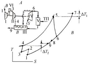
The development of the gas-turbine unit is based on the wellknown schema with the location of the combustion chamber after the turbine. The atmospheric pressure chamber is well conformed with the atmospheric pressure reactor-gasifier: to enter the fuel gas into the combustion chamber the use of a low-pressure circulator is sufficient. The use of puer air for the turbine operation excludes erosion damage of the turbine blades. The air is heated to the working temperature before the turbine in an air-gas heat-exchanger. The source of heat are the thermal gases, flowing out of the combustion chamber. The high temperature air-gas heat-exchanger acts as a regenerator with a regeneration rate of 100 % (due to the fact that the temperature of the air at the entrance of the combustion chamber equals to the temperature of the air after the turbine) and as a combustion chamber, raising the temperature at the regenerator exit to the temperature before the turbine. To implement the process of heat transfer the temperature in the combustion chamber exceeds the temperature before the turbine on the value of the limit temperature difference. The heat resistant alloy of VWX FY-98 type allows to raise the temperature before the heatexchanger matrix up to 1300 K and the air temperature at the turbine entrance to 1200…1250 K accordingly. The gas-turbine unit schema is of a regeneration type. Intercooler is introduced between compressors to improve efficiency and specific power. The principal schema of gasturbine unit and gas turbine cycle are given in figure.
The stoichiometric coefiicient L is determined by the elemental
Z[\][^_V_[` [a VWX bX`XcdV[c bd^ e_c afXg cdV_[ h iX]X`i^ [` VWX composition of the gas, the air temperature Ta at the entrance of the combustion chamber, the air temperature Tg at the exit of the combustion chamber, the heat capacity of the combustion products and is calculated through the solution of the combustion equation. Based on the combustion equation solution nomograms and tables, used in
71
engineering calculations, are made for industrial fuels with stable composition and properties (gasoline, natural gas, etc.). The combustion equation solution for the fuel with arbitrary composition is made using a specially developed computer system. The equation solution for fuel composition (table 1) in graphic form is given in Fig. 2.
Fig. Principal schema and Gas Turbine Cycle: A – schema, B – cycle, I – Low pressore compressor; II – high pressure compressor; III – air heat exchanger; IV –turbine; V –combustion chamber (all another figures correspond each others
The characteristics of the generation gas of municipal solid waste gasification
Indicator name |
Identification |
unit |
value |
Fractional composition (by weight) |
H2O |
% |
36,619 |
|
H2 |
% |
0,844 |
|
CO |
% |
9,188 |
|
C H4 |
% |
0,823 |
|
C2 H5 |
% |
1,096 |
|
C O2 |
% |
14,488 |
|
N2 |
% |
37,822 |
Lower heating value |
QHP |
kJ/kg |
2866 |
Stoichiometric coefficient |
L0 |
Kg/kg |
0,818 |
Gas constant |
Rnc |
J/kg.K |
378,47 |
72
The features of the combustion process of the low-calorie generator gas are demonstrated on a concrete example of a gas-turbine unit (Fig. 1) using the following data: air temperature after the highpressure compressor T4 = 416K, air temperature before the turbine T5 = 1173 K, air temperature after the turbine T6 = 750K, gas temperature after
the combustion chamber T7 = 1273K, stoichiometric coefficient L = 0,819, excess-d_cZ[Xaa_Z_X`VhjO* *WXdVZd]dZ_Vk[abd^lp = 1275 J/kg.K, heat
capacity of air Cp = 1070 J/kg.K, fuel gas consumption GT =1 kg/sec. The computing results are given below.
Heat power to increase air temperature from 416 to 1173 K 1987715 w,
Gas temperature at heat exchanger exit 821.64 K,
Non-used gas temperature potential 821,64 –416 =405,64 K, Taken for use temperature potential 405,64 – 100=305,64 K, Gas heat power to be used for heating excess air 1343174 w, Excess airflow, which may be heated by gas 1,685 kg/c
The excess air has to be used for additional power production. It flows through compressors, air heater, air turbine and directed then to the gas duck of the air heater, as it shown by dash-line on fig 1.
References
1.( F L m(4 + 3& 68 G : 7 3 (4$% .$5 + ( '& + &$&4(2&& .6, 36 6, & 7 /6n$6, , . / . / :(4&I&'(2&& ;; F &' > '. :. ,. +-( &/. < o(+/( (– 2012. –
– C. 134–144.
2.'&3& ) 0 ( @ 7 '(4($8 7 2 ( : ( &5 +:$. .- : 7$& ( 7 &4$% : G$/ : ( ( '(/ : ( &5 :(4 + 3& 8 + ( '& ;; >$. ? 68 (+@-, &@ '&8 &'
> '. :. ,. +-( &/. .<. o(+/( (. <$. H77-51038. 03 /(
2012 :.
73
THE OXYGEN PARTIAL PRESSURE INFLUENCE ON THE GAS DIFFUSION ELECTRODE CHARACTERISTICS OF THE ALUMINUM-AIR BATTERIES
A.A. Polikarpov
Moscow Aviation Institute (National Research University)
One of the notable features of oxygen as an oxidizer (cathodic material) in the metal-air batteries is the need of its constant flow through the gas chamber of a battery. That happens because the oxygen partial pressure (oxygen concentration) is reduced in the reaction zone due to its constant consumption in the current-forming reaction. It leads to the deterioration of the current-voltage characteristic of the gas diffusion cathode (GDC) as well as the whole battery characteristics deterioration. The GDC potential is expected to be changed under the Nernst equation during the changing of the oxygen partial pressure in the gas chambers of a battery. In this work the oxygen partial pressure influence on the GDC potential of the aluminium-air chemical current sources (AA CCS) was investigated.
The current-forming reaction of the AA CCS could be evaluated by next equation:
4Al + 3O2 + 6H2O Al(OH)3. |
(1) |
An alkali or neutral solutions are usuallu used as the electrolytes for AA CCS In these electrolytes an electrochemical reaction on the GDC is:
O2 + 2H2O + 4e 4OH–. |
(2) |
In the acid solutions: |
|
O2 + 4H+ + 4e 2H2O. |
(3) |
It is obvious that electrolyte’s type does not influence on the oxygen partial pressure in the gas chambers of AA CCS.
74
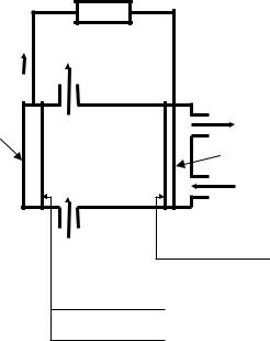
The fundamental scheme of AA electrolyte is submitted on the Fig. 1. showed in place where it does.
CCS with flow of the alkali The main processes in cell is
|
|
LOAD |
|
|
H2O + NaOH + Al(OH)3 + H2 |
||
|
e |
|
|
|
|
|
Air 2) |
Anode |
Al(OH)4 Al(OH)3 + OH |
||
|
|
|
GDE |
|
|
|
Air 2) |
|
H2O + NaOH |
O2 + 2H2O + 4e 4OH |
|
|
Al + 4OH Al(OH)4 |
+ 3e |
|
Summary: |
2H2O + 2e H2 + 2OH |
||
|
4 Al + 6 H2O + 3 O2 4 Al(OH)3 |
||
Current-forming reaction: |
|||
Reaction of the corrosion: |
2 Al+ 6 H2O 2 Al(OH)3 + 3 H2 |
||
Fig. 1. Scheme of the aluminium-air chemical current source with alkali electrolyte
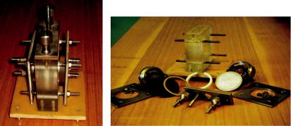
The general view of the laboratory thermo controlled cell, in which was realized experimental research, is showed on Fig. 2 and 3.
The gas chamber of the GDC of this cell exclude the possibility of the work gas and atmosphere convective mixing. The controlled inflow of the atmospheric air is provided with the goal to compensate pressure changing into the gas chamber because of oxygen consuming. In the research was used the hydrophobic graphitized carbon GDC produced by Joint Institute of High Temperatures of Russian Academy of Sciences. 4M NaCl solution was used as the electrolyte, because it is
75
accessible, easy to produce and safe to use. The cell thermo stating was provided by the water circulation from thermostat.
Fig. 2. The general view |
Fig. 3. Structure of the laboratory thermo |
of the laboratory thermo |
controlled aluminium-air cell |
controlled cell |
|
The method of experiments was that. The electrolyte is poured in the assembled cell and thermostat heated it. Then the cell connected to thermostat. The gas chamber was carefully blown by air by using diaphragm-type compressor. After that the cell is kept standing for the few minutes for setting equilibrium humidity of the gas in the gas chamber. The electrolyte bridge of the reference electrode was set so that Luggin capillary was contacted with surface of the GDC. It is necessary to exclude ohmic losses from measuring potential.
The measurements were realized in galvanostatic mode, current densites value was 250, 500 and 750 0/m2. The temperature of the electrolyte was 303 and 333K. Galvanostatic mode and GDC potential registration were provided by potentiostat. The potential was registered vs. Ag/AgCl saturated reference electrode.
Oxygen is spent in result of the reaction and as a result the partial pressure reduced. The potential change depending on time can be described by Nernst equation. As shown in the Fig. 4 the potential of the GDC is almost constant in the beginning, it slowly falls.
76
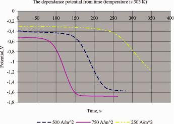
Fig. 4. Experimental curve of the dependence potential of the gas diffusion cathode from time with different current density. Temperature is 303 K
After some time the potential rapidly decline, because the partial pressure (concentration) is very low. From pic. 4 we can see that speed of the decline potential GDC is changed. That happens because the oxygen in chamber is completely consumed and new reaction is necessary instead of finished to provide the current. This reaction is the reaction of hydrogen evolution on GDC. If we approximate the resulting curve and calculate point of inflection the calculating potential correspond to potential of hydrogen evolution on GDC taking into account polarization of the electrode.
As expected the dependence in total is not changed during current density and temperature change. It was changed just time of experiment. In mathematical model of the experiment we calculate the concentration of oxygen in chamber using the Faraday equation and perfect gas law. It is quite acceptably with such conditions of the environment and do not cause of considerable error in the calculation. The resulting graphics show dependence potential of the GDC from partial pressure of the oxygen (Fig. 5). It was main aim of researching.
77
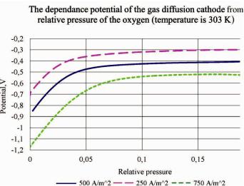
Fig. 5. The dependences between the relative pressure of the oxygen in the chamber and potential of the gas diffusion cathode with different current density
This dependences permit to define the range of oxygen pressure change in which we can ignore its influence on electrode potential change. If we use oxygen from air changing the partial pressure of the oxygen right up to 50 % from initial the changing of the electrode polarization do not exceed 5 %. The pressure reducing will cause the accelerating increase of the polarization.
In the end we realized the control measurement on the pure oxygen. The pure oxygen caused some changes in the experiment realization. The oxygen kept in the oxygen bag which connected with the gas chamber by means of hose. We aim to the careful blow oxygen through the chamber, so the speed of blow was very low. It was necessary to define criterion to consider, that the pure oxygen is presents in chamber. For this it was prepared the simple volume-meter. The required volume of the oxygen which must pass through the gas chamber to consider that in the chamber was pure oxygen is determined after some experiments.
78
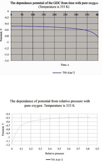
After control measurements data processing was found that the data agree with received during work with the oxygen from air. It is submitted on Fig. 6 and 7.
Fig. 6. Experimental curve of the potential dependence of the gas diffusion cathode from time with the pure oxygen. Temperature is 333 K
Fig. 7. The dependence of potential of the gas diffusion cathode from relative pressure with pure oxygen. Temperature is 333 K
79
The obtained data of GDC potential dependence from oxygen partial pressure in a gas mixture allow to optimize the gas channel geometry and minimize required air consumption, which provides equability in the work of GDC as well as the whole AA CCS. The research results could be also used in the design for any CCS types using air (or oxygen) as an oxidizer.
80