

01 POWER ISLAND / 02 H2+NH3 / Royal Swiss 2024 Techno-Economic Analysis of Wind Power-to-Hydrogen
.pdfFigure 10. Illustration of AWE and its operating principles [45].
2.8.1.2 Proton Exchange Membrane Electrolyzer
The Proton Exchange Membrane (PEM) electrolyzer was developed in 1966 [15], in order to overcome the limitations and disadvantages of AWE. This technology possesses desirable properties such as high energy efficiency, production of ultrapure H2, high current density (>200 A/m2), compact design and fast response time (flexible dynamic operation). However, it also possesses a couple of disadvantages, such as, expensive noble metal based electrocatalysts in electrodes (e.g., cathode is a Pt/Pd-based catalysts and anode is a RuO2/IrO2-based catalysts) and low durability [15][43].
The working principles of PEM electrolyzer involves electrochemically dissociating deionized water once in contact with the anode to produce protons (H+), electrons (e-) and oxygen gas (O2) according to reaction (5). This reaction process is known as oxygen revolution reaction (OER) due to the production of oxygen gas. The electrons will leave the anode by traveling through an external power circuit to the cathode. Simultaneously, protons will travel from the anode to the cathode electrode, however, via a thin solid polymer membrane (e.g., Nafion, Fumapem), which functions as an electrolyte (proton conductor) that separates the two electrodes from each other. The protons will re-combine with the electrons at the cathode to produce hydrogen gas as seen in reaction (6). This reaction is known as the hydrogen evolution reaction (HER) due to generating hydrogen gas. The overall cell reaction is expressed in reaction (7). The applied DC current density to initiate this non-spontaneous process, is between 10000 and 20000 A/m2 and the operating temperature is 50–80 . A PEM electrolyzer and its principles are illustrated in Figure 11 [15][43].
Anode: |
H O → 2H+ + |
1 |
|
O + 2e− |
(5) |
||||
|
|
||||||||
|
2 |
|
2 |
2 |
|
||||
Cathode: |
2H+ + 2e− → H |
|
(6) |
||||||
|
|
|
2 |
|
|
||||
Overall: |
2H O → H |
|
+ |
1 |
|
|
O |
(7) |
|
2 |
|
|
|||||||
|
2 |
2 |
|
2 |
|
||||
|
|
|
|
|
|
||||
Figure 11. Illustration of PEM and its operating principles [45].
29

2.9 Compressor
A compressor is a mechanical device that is used to increase the pressure of a gas by reducing its volume. This is accomplished by compressing the gas until the desired pressure is obtained. As the result, the density of the gas increases, and therefore more gas can be stored in the same volume [46]. Therefore, compressors serve an important role in enabling storage and distribution of gases, such as hydrogen, which has a low density at standard conditions.
There are several types of compressor technology, such as, reciprocating, centrifugal, rotating piston, oscillating compressors. These variants operate differently due to varying working principles and construction design. A reciprocating compressor involves using a piston to achieve high pressures, whereas lower pressures are normally obtained using a centrifugal compressor. Some centrifugal compressors use multistage compression and can be applied for large volume flow rates around 50000 Nm3 and are thus suitable for large-scale applications in industries [46].
Moreover, the operation of a compressor can be divided into the following categories: adiabatic and isothermal compression. Adiabatic compressors involve increasing the gas pressure, where no heat-exchange between the system and surroundings takes place. A simplified calculation of the compression work (shaft power) for an adiabatic compressor is found in equation (8). The isothermal compressors involve compressing a gas in multi-stages at a constant temperature. In such cases, a cooling-system is required due to heat being released. The shaft power of an isothermal compressor can be expressed according to equation (9) [46].
|
|
|
|
|
|
|
γ |
|
|
|
γ |
RT1 |
(( |
P1 |
) |
γ−1 |
−1) |
||
Wadi = |
γ−1 |
P2 |
|
||||||
|
|
|
|
|
(8) |
||||
|
|
ηadi |
|
|
|||||
|
|
|
|
|
|
||||
Wiso = nRTln ( |
P1 |
) |
(9) |
||||||
|
|||||||||
|
|
|
|
|
P2 |
|
|
|
|
Where γ is the specific heat ratio of a gas and R = 8.3145 JK-1mol-1 is the ideal gas constant. The compressor’s efficiency drive (ηadi) is commonly between 0.75 and 0.85. The temperature [K] and pressure [Pa] are expressed as the variables T and P. The amount of gas expresses in moles [Mol] is denoted as n [46].
The capital cost of a compressor is related to its capacity and technology. It is difficult to estimate a real general investment cost of a compressor, since the literature often include other equipment in the capital cost, e.g., compressor coupled to an on-site storage, as seen in Table 8 [42]. Table 8 shows the cost of different compressor capacities suited for large scale applications. However, some sources have provided a way to relate the capital cost of a compressor to its capacity and shaft work. This relation is expressed in equation 12, in chapter 3 [47].
Table 8. Investment costs (CAPEX) for compressor for large scale application including short term (on-site) storage in year 2020 [42].
Capacity |
CAPEX |
Power Consumption |
||
|
|
|
|
|
|
|
|
|
|
1168000 |
[kg/year] |
3.889 |
[m€] |
0.399 [kWh/kg] |
16940240 |
[kg/year] |
16.989 |
[m€] |
0.399 [kWh/kg] |
38663759 |
[kg/year] |
38.775 |
[m€] |
0.399 [kWh/kg] |
|
|
|
|
|
30
2.10 Storage
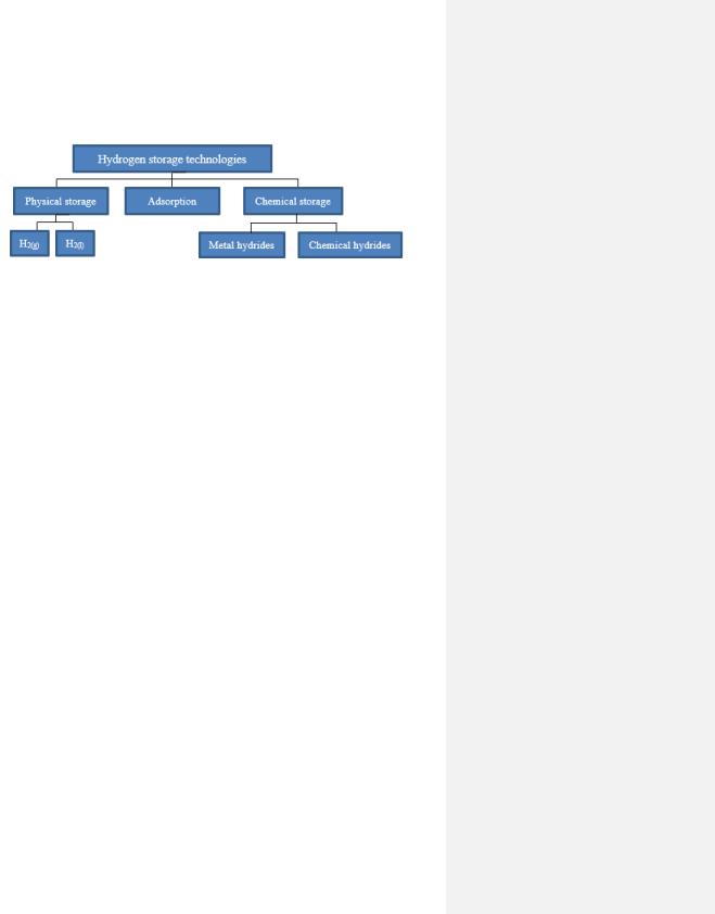
Hydrogen has a highly reactive nature and possesses a low density, which makes it a challenging gas to store. There are several storage methods, and these can be categorized as seen in Figure 12.
Figure 12. Types of hydrogen storage technologies [11].
Some of these storage categories are mature and commercially available, while others are still in the development phase. This report primarily focuses on the physical storage of compressed gaseous hydrogen as the targeted storage approach. However, an overview of the other storage methods will be presented below.
2.10.1 Adsorption
The adsorption storage method involves an adsorption process, where physical van der Waals bonding between molecular hydrogen and the pores at the surface of a solid material (often carbonbased) takes place. The solid materials used can for example be porous polymeric materials, metalorganic frameworks (MOFs), and zeolites. Multilayer of hydrogen adsorptions are possible; however, the strength of the adsorption will decrease as the number of layers increases. Furthermore, in order obtain a significant hydrogen storage density, parameter such as high pressures (between 10-100 bar) and cryogenic temperatures (77 K) must be applied due to the weakness of van der Waals forces. Liquid nitrogen is commonly used as a refrigerant [11].
2.10.2 Chemical Storage
As seen in Figure 12, the chemical storage can further be divided into the following two subcategories metal hydrides and chemical hydrides. There are three types of metal hydrides groups: binary hydrides, intermetallic hydrides, and complex metal hydrides. Nevertheless, the overall storage process for a metal hydride, involves hydrogen either being directly chemically bonded to a metal atom, e.g., magnesium (Mg) or aluminum (Al), (elemental metal hydrides and intermetallic hydrides) or an alloy (complex metal hydrides) e.g., lanthanum-nickel (LaNi5). An example of a promising metal hydride is sodium borohydride (NaBH4). This type of bond is much stronger than the physical bond of adsorption, which is described in section 2.10.1. In contrast, there are no metallic elements in chemical hydrides that may be liquid (e.g., methanol or formic acid) or gaseous (e.g., ammonia or methane). A special form of the liquid chemical hydrogen carriers are the liquid organic hydrogen carriers (LOHC), in which the carrier is liquid in both its hydrogenated and dehydrogenated form [11].
31

2.10.3 Physical Storage
Physical storage offers the ability to store hydrogen in its molecular form with a high purity. This is achieved by storing hydrogen either as liquid or compressed gas in an appropriate storage tank. Furthermore, physical storage is the most well-established storage technology today, where the tanks are commercially available in different construction designs. Therefore, physical storage is commonly employed regardless of application scale [11][48]. Moreover, physical storage can be utilized as both overand underground storage. Underground storage, also known as geological storage, includes for example engineered cavities (artificially made underground storage) and salt caverns. However, underground storage is limited by geological conditions. Among the benefits of underground storage are the low specific construction cost, rapid withdrawal and injection rates, low leakage rates, and low risk for hydrogen contamination. An aboveground storage is an alternative to geological storage due to being geographically flexible. It involves operating a tank above the ground, typically situated close to the production facility. These types of storages mainly consist of metal. The storage material will ensure the stability of the tank and for most applications it is also important that it does not contaminate the hydrogen. In most cases, inspection of the storage system is easier to perform on an aboveground storage than on an underground storage [11].
2.10.3.1 Liquid Hydrogen Storage
Liquefaction of hydrogen has the advantage of attaining high storage densities already at atmospheric pressure, where the saturated liquid hydrogen has the density of 70 kg/m3 at 1 atm [11].
Liquefaction is a mature practice that is globally employed. However, the drawback is the energyintensive process required to obtain the liquid hydrogen due to two factors. Firstly, hydrogen has an extremely low boiling point (20 K at 1 atm), and secondly hydrogen needs to be cooled down to temperatures below 200 K to allow for liquefaction by a throttling process (adiabatic, isenthalpic expansion). The reason for this is the negative Joule Thomson coefficient at temperatures above 200 K, which means that the temperature of hydrogen increases when expanded isenthalpically. Another drawback is the evaporation of hydrogen, which occurs when heat is transferred from the environment to the stored liquid hydrogen. To remove the pressure build-up occurring inside of the storage vessel, which is caused by the evaporated hydrogen, the tank must be vented. This is known as “boil-off” and is usually measured as the percentage of stored hydrogen that is lost per day (boil-off rate) [11].
A proper storage tank for liquid hydrogen should have a spherical construction design to minimize the surface-to-volume ratio, which can reduce the boil-off rate. Other construction methods are for example implementing double walls to obtain vacuum in-between. The design of these tanks is usually relatively complex; however, there are some indications that at large scales, liquid hydrogen tanks cost less per weight of hydrogen than compressed hydrogen gas tanks [11].
2.10.3.2 Compressed Gaseous Hydrogen Storage
Compressed hydrogen storage (CGH2) is the most established storage technology. This technology involves employing a storage vessel primarily constructed from steel, although some also include composite materials, to store gaseous hydrogen. There are different types of vessels available, and these are categorized into four different tank types (Type I, Type II, Type III and Type IV) that operate at different pressure levels [49].
32
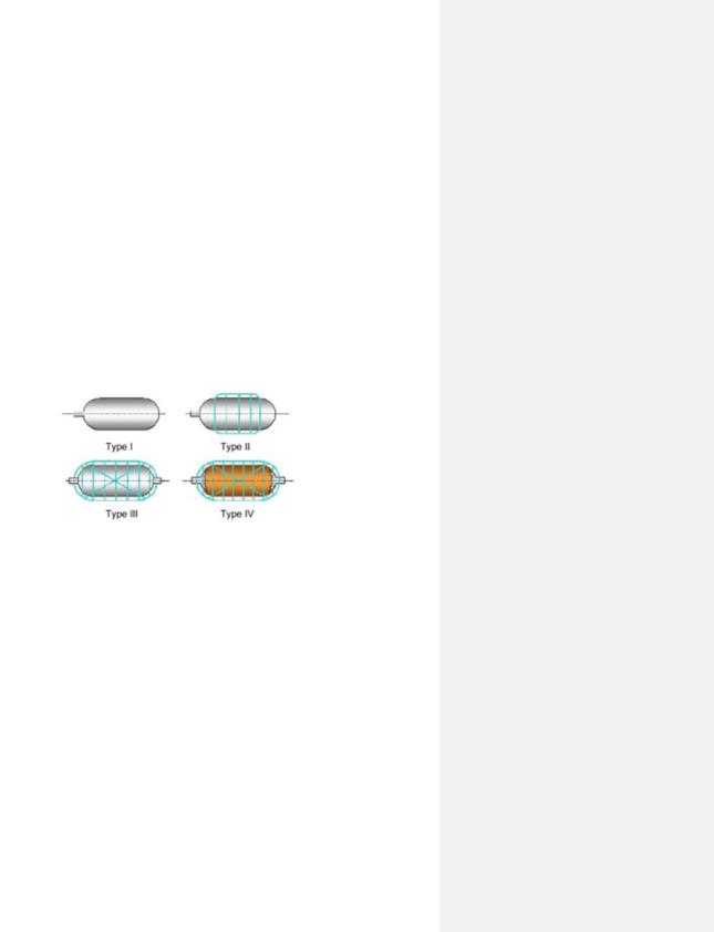
When selecting which tank type to utilize, the specific application in which it is intended to be employed for, must be considered. For instance, Type I with operational pressure of 200–300 bar, can be built in large sizes and therefore is the most commonly occurring tank within the industry for large-scale production. It is the heaviest tank, which is one of few reasons why it is more suitable for stationary applications (on-site storage) than for hydrogen storage in vehicles. Tank I is the least expensive tank variant, which makes it cost-effective. Next, tank Type II with operational pressure of 300–350 bar, is lighter and more expensive than Type I. Similar to Type I, Type II is also more suitable for stationary applications than mobile applications. This is due to these two tank types having a low hydrogen storage density and a higher risk to encounter hydrogen embrittlement challenges. The latter is a slow process in which hydrogen makes a material weak [49].
Tank Type III and IV, with operational pressure of 450 bar and 700–1 000 bar, respectively, are more convenient for mobile applications, such as storage tanks in FCEV. This is due to a couple reasons; both Type III and IV avoids the hydrogen embrittlement due to the wrapping liners that functions as a hydrogen permeation barrier. Additionally, the liners also act as a load-bearing element and increase the mechanical resistance by approximately >5% [49]. Tank Type III costs more and is lighter than Type I and II, however Type IV is the lightest and most expensive tank of these types. This is due to the fact it consists of carbon fiber, which contributes up to 75% of the tank price. In addition, Type IV can endure high pressures of up to 1 000 bar [49][50]. A general schematic illustration of these tanks can be seen in Figure 13 below. Additionally, estimated investment cost (CAPEX) for each tank, is listed in Table 9.
Figure 13. Sketch of different tank types for physical storage of hydrogen gas [51].
Table 9. Investment cost for different types of compressed gaseous hydrogen storage [52][53][54].
Tank Type |
CAPEX |
|
|
|
|
|
|
|
Tank Type I |
490–500 |
[€/kg] |
Tank Type II |
600–800 |
[€/kg] |
Tank Type III |
1250 |
[€/kg] |
Tank Type IV |
>2000 [€/kg] |
|
|
|
|
2.11 Hydrogen Refuel Station
A hydrogen refueling station (HRS) is where hydrogen fuel cell vehicles (FCEV) can be filled with hydrogen. This type of station comprises various components, where the main ones are cascade storage, compressor, refrigeration system, and dispenser. A cascade storage system is a high-pressurized gas cylinder storage system, where its configuration is made up of multiple tanks operating at varying pressure levels. These tanks are categorized as a low-pressure tank (LPT, 350–500 bar), medium-pressure tank (MPT, 350–500 bar) and high-pressure tank
33
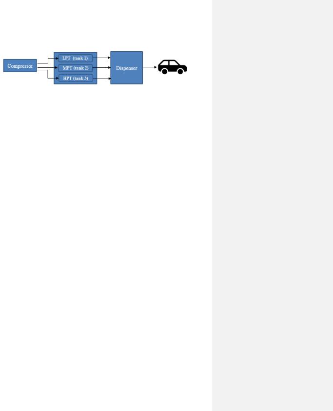
(HPT, ≥900 bar). These tanks are interconnected through a network of pipelines and are linked to a compressor for filling of the tanks [55][56]. A simplified schematic illustration of the HRS can be seen in Figure 14.
Figure 14. General sketch of HRS.
The operating process of HRS can be divided into two sections: the compressor system and the refueling system. The former system includes the process of refilling the storage tanks and the latter system involves refueling the FCEV. The refueling process is initiated when a vehicle is connected to the dispenser’s nozzle. At first, the size of the vehicle’s tank is determined and then the refilling process takes place. To provide a regulated gas flow during the refilling process, a suitable average pressure ramp rate is set based on the ambient temperature and vehicle’s tank pressure [55][56].
The refueling process starts with opening the LPT so a hydrogen stream can flow to the vehicle. This will activate the compressor system as the compressor will now start delivering hydrogen to the stream. During this step, if the amount of hydrogen delivered to the steam is greater than the amount required for the refueling, then the excess hydrogen will be stored in the LPT. The refueling process will continue to proceed in this matter until a switch from the LPT to the MPT. This is due to the MPT having a higher operating pressure. Simultaneously, the compressor keeps filling the LPT with hydrogen until it regains its initial condition. Finally, the HPT takes over the hydrogen refueling process to maintain the pressure ramp rate due to the pressure of the MPT being too low and needs to recover back to its initial state by the compressor. Once the total refueling process is completed, the vehicle can be disconnected. The compressor will continue operating the recovering process for the HPT, until the initial state of this tank is regained as well. In this way, the HRS station will be ready for a new refueling process [55][56].
The HRS follows the SAE J2601 protocol as it provides an efficient and safe approach for highspeed hydrogen refueling. The protocol states among other things, that the compressed hydrogen has to be pre-cooled by a refrigeration unit down to -40 °C before injected into the tank, to obtain a fueling process between 3–5 minutes without causing an overheat of the tank. Therefore, a refrigeration system must be integrated into the dispenser [55][56].
The investment cost of HRS is somewhat difficult to estimate since the hydrogen market and infrastructure are not well-established yet. However, research conducted by HyCoGen, has estimated that the cost of HRS for fueling 350-700 bar on-board storage is between 1 and 5 m€. Additionally, a refueling station for 350 bar on-board storage is cheaper than the corresponding
for 700 bar on-board storage. Moreover, stations with high capacity (kg H2/day) are more expensive, however, if frequently used it can become cost-effective. A large frequently used station would add approximately 3.6 €/kg to the final hydrogen price, where in the future it is expected to be reduced to 1.8 €/kg [14].
A report from Swedish Knowledge Centre for Renewable Transportation Fuels (f3), has estimated the investment cost for HRS for fueling a 700-bar on-board storage for the year 2020. The estimated cost with respect to the HRS capacity is listed in Table 10. This cost includes compressor, storage, and dispenser [57].
34
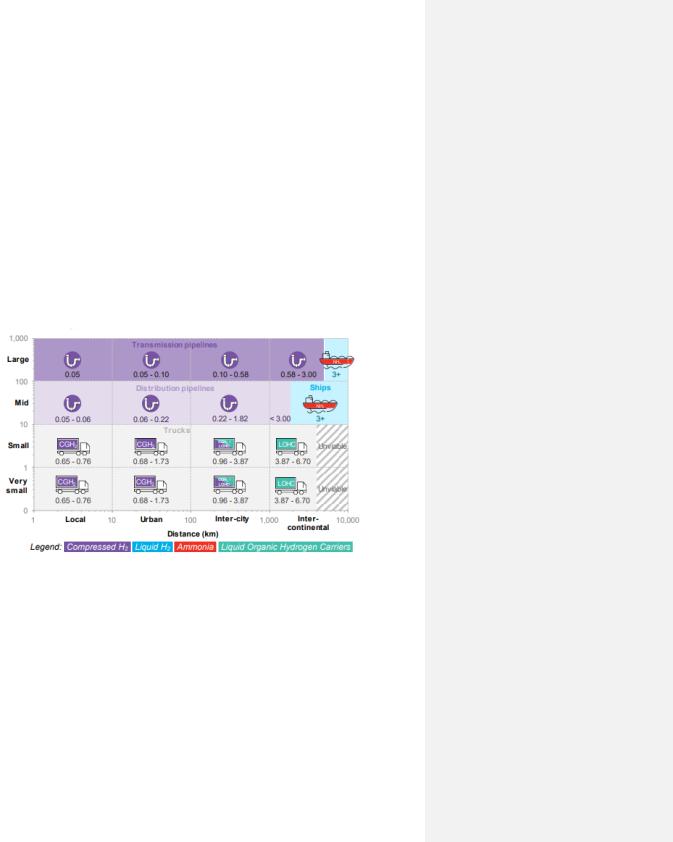
Table 10. Estimated Investment Cost for Hydrogen [57].
Hydrogen Capacity |
CAPEX |
|
|
|
|
|
|
|
200 |
[kg/day] |
1.3 [m€] |
1000 |
[kg/day] |
2.5 [m€] |
|
|
|
2.12 Hydrogen Distribution
As previously mentioned, one kilogram of hydrogen occupies a volume exceeding 11 m3 at standard conditions. Therefore, prior to transporting large quantities, hydrogen must either be pressurized and delivered as a compressed gas (CGH2) in high-pressure cylinders, as liquefied hydrogen (-253°C) stored in cryogenic vessels, or as chemically absorbed to an organic compound. Thereafter, an appropriate distribution method is assigned. To assign a suitable delivery method, different factors within the technical and economic aspects must be considered. These factors are for example the quantity of hydrogen to be transported, delivery costs, transportation distance and infrastructure. A summarization of these factors is illustrated in Figure 15, where the transportation method is related to the travel distance and cost.
Figure 15. A visual presentation of H2 transportation costs with regards to distribution distance [km] (x-axis) and volume [tons/day] (y-axis). Note that costs include movement, compressor and the storage used [58].
As seen in the Figure 15, for small hydrogen quantities and short travel distances, delivering hydrogen as a compressed gas is most suitable. For longer distances (intercontinental) and small quantities, hydrogen is suggested to be distributed chemically by using liquid organic hydrogen carriers (LOHC). However, despite that LOHC is a cheaper long distance distribution option compared to liquid hydrogen, LOHC is less likely to be selected over the commercially developed liquid hydrogen as a transportation option. Therefore, on such occasions, liquid hydrogen replaces LOHC in Figure 15.
A common denominator for all these distribution methods, is delivering hydrogen by trucks. The drawback of delivering hydrogen by trucks is the high delivery cost and expensive capital cost of these tube trailers. The capital cost of a tube trailer depends on its storage capacity and operating pressure. Overall, the cost can be reduced by using tubes with high operating pressure as it equals
35

an increase in storage capacity; ultimately fewer trucks are needed for hydrogen distribution. However, the purchase price of the truck will increase as well. The capital cost for a trailer tube with a storage capacity of 370 kg H2 and an operating pressure of 200 bar is estimated to be 0.185 m€ [59][60]. Moreover, if infrastructure for distribution of hydrogen via pipelines is available, such a distribution approach is preferable due to the low specific cost. Distribution of hydrogen by pipeline can be applied both for small and large quantities regardless of the travel distance. However, pipelines also have some drawbacks such as the risk of hydrogen embrittlement and leaks. Thus, factors such as the material of the pipeline need to be considered. Lastly, distribution of hydrogen can also take place in a form of shipping when large quantities need to be delivered intercontinentally.
36

CHAPTER 3. CASE STUDY
As previously stated, the aim of this case study is to investigate if and at which electricity and hydrogen price, a PtH plant has the potential of becoming economic profitable. One of the main determining factors in this investigation is the dynamic power production profile of the offshore wind farm, since wind power also affects the volatility of the spot prices. This means that at periods of high wind currents, low spot prices are usually expected. On the other hand, at low wind currents less electricity will be produced, which results with higher spot prices. Therefore, in theory, a profitable hydrogen production could be obtained during periods of high wind currents as it may result in lower spot prices. However, according to the second determining factor, which are the customers, the green hydrogen price must be low enough in order to become competitive to the already low-priced competitors e.g., diesel. Thus, despite low spot prices, the second determining factor (the costumers) can reduce the chances for green hydrogen of becoming profitable within the transport sector, given today's high equipment and operational costs of its production facility. This is due to the current hydrogen infrastructure not being well-established. This will, in turn, further complicate the process of determining a competitive selling price for the green hydrogen and still ensure an economic profitability, while simultaneously predicting an accurate total capital cost of a hydrogen production facility. Nonetheless, it is of interest to estimate whether green hydrogen has the potential of becoming economic viable based on the data available today, if an optimal utilization of the electricity produced from wind energy, is practiced. This means to determine where an optimal utilization of the electricity lies by carefully considering the spot prices. Therefore, the strategy of this report will be to divide the utilization of electricity, based on the spot prices, into two alternatives. The first alternative involves low spot prices, where the producer will choose to power the H2 production facility due to it being more profitable. The hydrogen production will be scaled according to the number of hours where the spot prices are low. During these hours, wind turbines must generate a power [MW] at least of what the electrolyzer’s capacity is, otherwise hydrogen production will be scaled down to zero; regardless of the spot price. This is since static operation of the electrolyzer is assumed in this report. The second alternative involves high spot prices, during which the producer will choose to sell the electricity and electricity certificates to the spot market due to being more profitable. During the second alternative, no hydrogen production will take place.
The two alternatives will be compared by combining two types of economic models, contribution margin, and opportunity cost, as described in section 5.1.2.4. These models will lay the foundation of determining the price intervals of high and low spot prices, respectively. In this report, the sector of interest is the transportation sector due to its high carbon emissions and the great interest in a transition to green fuels. Moreover, this study is based on empirical data collected from the years 2019, 2020, and 2021. During year 2021, the spot price has been highly volatile due to various external factors, making this analysis even more intriguing to undertake.
3.1 System Overview
The location of the Power-to-Hydrogen plant will be situated in bidding area two, and it will consist of an offshore wind plant that is both connected to the grid and to the electrolyzer, as schematically illustrated in Figure 16. The operational principles of the Wind Power-to-Grid and
Power-to-Hydrogen system will remain constant. However, the size of the H2 production facility will vary, depending on the installed electrolyzer capacity.
37

Figure 16. Wind farm connected both to the grid and hydrogen facility by electric cables.
3.2 Offshore Wind Park
The construction of a hypothetical offshore wind farm is scheduled to take place in Gävleborg County, where the power site will be located in the Bothnian Sea adjacent to Gävle harbor. The choice of farm’s size is derived from a real Swedish offshore wind farm called Lillgrund, situated in the Öresund region. Therefore, in this report, the wind farm will host 48 wind turbines, where each will operate at varying wind speeds. These turbines will have a rated power of 2.3 MW, resulting in a total capacity of 110 MW. Furthermore, the features of these turbines will be a rotor with a diameter of 92.6 m, hub height of 65 m, and a minimum lifespan of 15 years. Furthermore, similarly to Lillgrund, the turbines will start producing power at a wind speed of 4 m/s, and obtain a nominal power at wind speeds of 12–13 m/s. The turbines will stop operating at wind speeds exceeding 25 m/s for safety reasons and to prevent excessive wear. However, once the wind speed reduces to a safe level, the turbines will resume operation [61].
In this report, the performance of the wind farm for the years 2019, 2020 and 2021 will be estimated through analysis of a vast dataset comprising both meteorological data and the turbines’ operational data. Real meteorological data was collected from a wind speed measuring station called Eggegrund A, due to its nearby proximity to the wind farm’s location. The data is available to obtain from the Swedish Meteorological and Hydrological Institute’s (SMHI) website, a
Swedish governmental agency. Moreover, according to SMHI, the year 2019 had 5338 hours of wind speed ranging between 4–25 m/s, while 2020 and 2021 had 5433 h and 6053 h, respectively [62].
To generate operational data of the wind plant, MATLAB was used to compute the power output of as a function of wind speed for all target years, where the real power output of Lillgrund was used as a reference (Table 11) [61]. In this report, power output [MW] will be used for two purposes: first to produce durability diagrams (Figure 19–21) and secondly to simulate the hydrogen production (Figure 30–44). The power output can also be used to produce a so-called power curve, which visualizes the variation in power production with wind velocity as shown in Figure 17. This relation visualizes the intermittence nature of the wind plant, which in turn will influence the spot prices as previous mentioned. Furthermore, Figure 18 shows generation of electricity obtained at different wind speeds for all years of interest.
38