

книги / How to Write a Research Paper in English
..pdfcharge of one section, number of sections and delay interval were selected as the relevant variables for analysis, which were recorded as X1, X2, X3 and X4 respectively.
3.2. Acquisition of Sample Data of Blasting Vibration Caused by Shallow Tunnel Excavation
Using numerical software LS-DYNA, the finite element model of cut blasting in shallow tunnel was established, as shown in Figure 1. 3994 is the number of selected surface feature points, from which sample data were obtained. The size of the model is 50m×30m×24m, and the length of the tunnel face without excavation is 24m. Charge diameter is 52 mm, length is 400 mm, mud plugging is 400 mm, single hole charge is 0.85 Kg.
Figure 1. Finite element model of cutting blasting in shallow tunnel.
The explosive material model is defined by JWL state equation:
Pcj = A(1− |
|
ω )e−RV1 + B(1− |
|
ω )e−R V2 +ω |
|
E (5) |
|
|
|
|
|||||
|
RV1 |
R2V |
|
V |
|||
where A, B, R1, R2, ω are input parameters, A=371.2Gpa, B=3.231Gpa, R1=4.15, R2=0.95, ω= 0.3; E is explosive energy, E=7Gpa; TNT is selected as explosive in this model, explosive velocity vd=6930m/s, density ρ0=l630kg/m3, explosion pressure Pcj=0.21Gpa.
The blasted rock mass is granite, and the constitutive model of rock mass is isotropic-elastic-plastic material. Its state equation is as follows:
p = ρoc v2 [1 + −(12 µ/ 2)v −αv32 / 2] |
2 2 + (µ α+ v)E (6) [1 − (s1 − 1)v + s v2 |
/ (v + −1) |
||
|
s v2 / (v + 1) ] |
|
|
|
where s1=l.5, s2=0, s3=0, γ=2.0 α=0.5 v=l/vo-1(vo is relative volume); the material parameters of granite are: Young's modulus E= 66Gpa, Poisson’s ratio µ= 0.23, density ρ0=2700kg/m3, wave velocity c=5268m/s, shear modulus G=23Gpa, hardening parameter n=0.25.
The mesh arrangement of cut holes is shown in Figure 2. Millisecond blasting of different parameters of charge of the first section, maximum charge of one section, number of sections and delay interval were simulated between 10 boreholes by setting different initiation sequence.
71
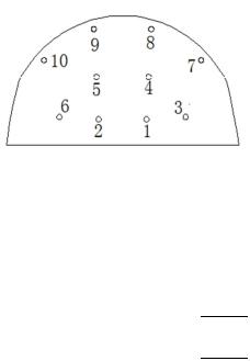
Figure 2. Diagram of mesh arrangement of cutting holes.
Table 1 is a sample of 13 groups of blasting vibration data obtained by using the numerical model to simulate various working conditions.
Table 1. Sample of blasting vibration data.
|
|
Relevant |
|
|
System Characteristic |
|
|
||||
|
|
Variables |
|
|
Variables |
|
|
|
|
||
No. |
|
X1 |
X2 |
X3 |
|
X4 |
Y1 |
Y2 |
Y3 |
Y4 |
|
|
(kg) |
(kg) |
(ms) |
|
(cm/s) |
(Hz) |
(cm/s) |
(%) |
|
||
|
|
|
|
|
|||||||
1 |
|
5.1 |
5.1 |
35 |
|
2 |
7.25 |
16 |
0.91 |
87.4 |
|
2 |
|
3.4 |
3.4 |
35 |
|
3 |
7.25 |
16 |
0.95 |
86.9 |
|
3 |
|
6.8 |
6.8 |
35 |
|
2 |
7.4 |
15.99 |
1.17 |
84.2 |
|
4 |
|
0.85 |
6.8 |
35 |
|
3 |
4.05 |
27.99 |
0.77 |
80.9 |
|
5 |
|
1.7 |
3.4 |
35 |
|
3 |
5.26 |
83.96 |
0.86 |
83.7 |
|
6 |
|
1.7 |
6.8 |
35 |
|
2 |
4.89 |
31.98 |
0.76 |
84.5 |
|
7 |
|
1.7 |
3.4 |
35 |
|
4 |
4.89 |
31.98 |
0.84 |
82.8 |
|
8 |
|
5.1 |
5.1 |
0 |
|
2 |
13.0 |
62.83 |
1.51 |
88 |
|
9 |
|
5.1 |
5.1 |
8 |
|
2 |
8.36 |
10.95 |
1.21 |
85 |
|
10 |
|
5.1 |
5.1 |
15 |
|
2 |
9.66 |
91.95 |
0.99 |
0.99 |
|
11 |
|
5.1 |
5.1 |
35 |
|
2 |
6.67 |
91.95 |
1.07 |
1.07 |
|
12 |
|
5.1 |
5.1 |
50 |
|
2 |
6.67 |
59.97 |
1.14 |
1.14 |
|
13 |
|
5.1 |
5.1 |
70 |
|
2 |
6.67 |
63.97 |
1.09 |
1.09 |
|
3.3. Calculation of Grey Relational Degree
In order to determine the positive and negative relation between the related variables and the system characteristic variables, the relation should be transformed by axial symmetry method. Explosion charge is negatively related with main frequency, number of sections and delay interval is negatively related with particle peak velocity, the relevant variables are positively related with average combined velocity and velocity attenuation rate. Initial data are usually transformed into dimensionless data with similar order of magnitude in the process of grey relational analysis, and the negative relation factors are transformed into positive
relation factors. Based on the sample data in Table 1, the grey relational matrix of the factors affecting blasting vibration was calculated with method of grey relational analysis, as shown in Table 2.
Table 2. Grey relational matrix of the factors affecting blasting vibration.
Relational |
X1 |
X2 |
X3 |
X4 |
|
Degree |
|
|
|
|
|
Y1 |
0.7792 |
|
|
|
0.6878 |
|
|
|
72 |
|
|

Y2 0.6857
Y3 0.7039
Y4 0.7281
∑2.8969
3.4.Analysis on Influencing Factors of Blasting Vibration Caused by Shallow Tunnel Excavation
Referring to the grey relational matrix of the influencing factors of blasting vibration in Table 2, superiority ranks analysis of the related variables were carried out, and the following conclusions can be drawn:
The superiority ranks of influencing factors of blasting vibration caused by shallow tunnel excavation in the order of high to low are: maximum charge of one section, charge of the first section, delay interval and number of sections; there is no optimal factor, and the maximum charge of one section is the quasi-optimal factor.
The superiority ranks of influencing factors of particle peak velocity for blasting vibration in the order of high to low are: charge of the first section, maximum charge of one section, delay interval and number of sections; combining with the comparative analysis of particle peak velocity of different charge of the first section in Table 1, it is shown that the charge of the first section is the main factor affecting the peak velocity of blasting vibration.
The superiority ranks of influencing factors of main frequency for blasting vibration in the order of high to low are: maximum charge of one section, charge of the first section, delay interval and number of sections; the maximum charge of one section is the main factor affecting the main frequency of blasting vibration.
The superiority ranks of influencing factors of average combined velocity and velocity attenuation rate for blasting vibration in the order of high to low are: delay interval, maximum charge of one section, charge of the first section and number of sections; delay interval is the optimal factor for the two system characteristic variables, which is also the main factor affecting the duration of blasting vibration. In the superiority ranks of the factors affecting the duration, the ranks of the factors affecting the average combined velocity and the velocity attenuation ratio show consistency, which indicates that the two parameters selected to represent the duration of blasting vibration are reasonable.
As one of the influencing factors of blasting vibration, the number of sections is not a quasi-opti- mal factor and the main influencing factor. Excessive increase of the number of initiation sections is not an effective means to control the blasting vibration effect in millisecond blasting.
4. Control Measures of Blasting Vibration Caused by Shallow Tunnel Excavation
Based on the above conclusions, the following measures are suggested to control the blasting vibration caused by shallow tunnel excavation:
To reduce the charge of the first section. Because the number of free surfaces is small and the initiation energy of the first section is too concentrated, the blasting vibration caused is large. At the same time, due to the serious shortage of compensation space after blasting, blasting rock is subject to greater resistance when it disperses, and the blasting effect is poor. Therefore, reducing the charge
73
of the first section can effectively control the blasting vibration intensity and improve the blasting effect.
To reduce the maximum charge of one section. The maximum charge of one section is the main factor affecting blasting vibration. Therefore, under the condition of constant total blasting charge, the blasting vibration intensity can be effectively reduced by properly increasing the initiation sections and reducing the maximum charge of one section.
To set up rational delay interval. For millisecond blasting of shallow tunnel, reasonable delay interval is more effective than increasing the number of sections. Cutting holes can be set as jump-off, which can prolong the interval between sections properly and prevent the superposition of blasting seismic waves, so as to achieve the purpose of vibration reduction. Cutting holes can be set as jumpoff blasting holes, which can prolong the interval between sections and prevent the superposition of blasting vibration waves, so as to achieve the purpose of vibration reduction.
5. Conclusion
The sample data of blasting vibration were obtained by establishing finite element model of cut blasting in shallow tunnel. Based on the sample data, the relational degree analysis was carried out for influencing factors of blasting vibration caused by shallow tunnel excavation with method of grey relational analysis. The analysis results show that: among the four relevant influencing factors, there is no optimal factor, and the maximum charge of one section is the quasi-optimal factor; the charge of the first section is the main factor affecting the peak velocity of blasting vibration; the maximum charge of one section is the main factor affecting the main frequency of blasting vibration; the delay interval the main factor affecting the duration of blasting vibration.
Based on the conclusion of grey relational analysis, the measures to control blasting vibration caused by shallow tunnel excavation were put forward, such as reducing the charge of the first section, reducing the maximum charge of one section and rationally setting up the delay interval.
There are many factors affecting blasting vibration caused by shallow tunnel construction. Only some of the factors were considered based on the numerical test model in this paper. It is suggested that field tests can be carried out to further analyze the influence of other factors such as number of free surfaces, hole network parameters and geological conditions.
Acknowledgements
The authors would like to acknowledge the financial support from the National Natural Science Foundation of China (51504082 and 51874123) and the Science and Technology Research Planning Project of Henan Province, China (152102310331).
References
[1]P. K. Singh. Blast vibration damage to underground coal mines from adjacent open-pit blasting [J]. International Journal of Rock Mechanics and Mining Sciences, 2002, 39 (8): 959-973.
[2]Qihu Qian, Shihai Chen. Blasting vibration effect [J]. Blasting, 2004, 21 (2): 1-5.
[3]Chengyu Xie, Zhouquan Luo, Nan Jia, Lixin Xiong, Guihai Cheng. Dynamic effects of open blasting vibration on adjacent buildings and measures for vibration reduction [J]. Journal of Vibration and Shock, 2013, 32 (13): 187-193.
[4]Ranjan Kumar, Deepankar Choudhury, Kapilesh Bhargava. Determination of blast-induced ground vibration equations for rocks using mechanical and geological properties [J]. Journal of Rock Mechanics and Geotechnical Engineering, 2016, 8 (3): 341-349.
74
[5]Wenzhuo Cao, Xibing Li, Ming Tao, et al. Vibrations induced by high initial stress release during underground excavations [J]. Tunnelling and Underground Space Technology, 2016, 53: 78-95.
[6]Shihai Chen, Shuaiwei Hu, Zihua Zhang, et al. Propagation characteristics of vibration waves induced in surrounding rock by tunneling blasting [J]. Journal of Mountain Science, 2017, 14 (12): 2620-2630.
[7]Nan Jiang, Tan Gao, Chuanbo Zhou, et al. Effect of excavation blasting vibration on adjacent buried gas pipeline in a metro tunnel [J]. Tunnelling and Underground Space Technology, 2018, 81: 590-601.
[8]Mesec J, Kovac I, Soldo B. Estimation of particle velocity based on blast event measurements at different rock units [J], Soil Dynamics and Earthquake Engineering, 2010, 30 (10):
1004-1009.
[9]Mingsheng Zhao, Kaishui Liang, Benwei Li. Influence of deck charge on time-frequency characteristics of a blasting vibration signal [J]. Journal of Vibration and Shock, 2012, 3l (7): 85-88.
[10]D. P. Blair. Blast vibration dependence on charge length, velocity of detonation and layered media [J]. International Journal of Rocks Mechanics and Mining Sciences, 2014, 65: 29-39.
[11]Junru Zhou, Wenbo Lu, Le Zhang, Ming Chen, Peng Yan. Attenuation of vibration frequency during propagation of blasting seismic wave [J]. Chinese Journal of Rock Mechanics and Engineering, 2014, 33 (11): 2171-2178.
[12]Zhengzheng Wang, Yangsheng Zhang. Numerical analysis for blasting vibration characteristics in tunnel excavation based on ALE algorithm [J]. Journal of Dalian University of Technology, 2017, 57 (3): 279-284.
[13]Zhiwen Li, Jianchun Li, Shengnan Hong, Haibo Li, Guokai Zhang. Theoretical analysis of blasting vibration zone considering viscous effect [J]. Journal of Vibration and Shock, 2018, 37 (17): 108-114.
[14]Sifeng Liu, Tianbang Guo, Yaoguo Dang. Grey system theory and its application [M]. Beijing: Science Press, 2013: 1-30.
[15]Zijun Li. Advance of study on application of grey system theory in China during 1992-2001[J]. Systems Engineering, 2003, 21 (5): 8-12.
[16]Dang Luo, Sifeng Liu. Study on the method for grey incidence decision-making [J]. Chinese Journal of Management Science, 2005, 13 (1): 101-106.
[17]Julong Deng. Basic method of grey system [M]. Wuhan: Huazhong University of Technology Press, 1988: 17-28.
75

Sample 3
Available online at www.sciencedirect.com Sci


 enceDirect
Procedia Engineering 182 ( 2017 ) 366 – 372
7th International Conference on Engineering, Project, and Production Management
Comprehensive Approach to Efficient Planning of Formwork Utilization on the Construction Site
Anna Krawczyńska-Piechna*
Warsaw University of Technology, Faculty of Civil Engineering, Mechanics and Petrochemistry, Łukasiewicza 1, Płock 09-400, Poland
Abstract
The paper presents a consistent approach to concrete works planning, which begins with formwork selection and ends with project scheduling. To work out the problem of formwork selection, selected MCDA methods are recommended. In order to apply them, the decisive criteria were recognized with a structured survey sent to contractors. The efficiency of formwork utilization is measured with a virtual cost of formwork under utilization, so when the formwork is available on the construction site but remains unused or when it should be struck but remains unremoved from the construction. Such measure was determined, after having analysed various criteria of schedule quality and optimality assessment.
© 2016 The Authors. Published by Elsevier Ltd. © 2016 The Authors. Published by Elsevier Ltd. This is an open access article under the CC BY-NC-ND license
Peer-review under responsibility of the organizing committee of EPPM2016. (http://creativecom- mons.org/licenses/by-nc-nd/4.0/).
Peer-review under responsibility of the organizing committee of EPPM2016
Keywords: formwork; monolithic concrete works; interactive planning; efficiency of formwork utilization
1. Introduction
Formwork is the largest single cost component of a concrete building’s structural frame and varies averagely between 35 and 45% of a reinforced concrete structure’s unit cost [1, 2]; for civil engineering structures it can reach even 60%. Formwork items are usually rented by the contractor to perform particular concrete woks. Therefore, considering their constructability and analyzing efficiency of their utilization at each stage of construction planning, in order to accelerate construction schedule or increase jobsite productivity, seems to be the smartest step to reduce lease costs and in consequence – total building works' costs.
76

*Corresponding author. Tel.: +4-824-262-4226; fax: +4-824-262-4226. E-mail address: krawczynskaa@pw.plock.pl
This brought about the idea to establish a new, consistent method of project planning which begins with formwork selection and ends with project scheduling, where formwork availability and utilization efficiency is being analyzed at once. The key issue to resolve the decisive and planning dilemmas settled in the research [2] was to identify problems and their constraints, that stem from specifics of the cast-in-place building technology. A thorough investigation on formwork selection problem, as well as project planning and scheduling methods was carried out. Its goal was to decide, whether it would be possible to adapt existing planning techniques to work out the solution for the subject matter. The whole planning method is explained in detail in [2], while the present paper describes a synthetic approach to the subject problem.
2. What influences on formwork utilization efficiency?
It can be easily stated, that having profound knowledge on monolithic concrete works’ technology and formwork systems’ features results in choosing an appropriate system to perform concrete works. This gives rise to: reduction of labor costs, improving the quality and safety of produced concrete, achieving faster work cycles [3]. Formwork selection is, thus, the first problem, that should be considered in order to improve formwork utilization on the construction site.
However, it is not the only one. The second issue is how to schedule works and plan formwork utilization effectively and how to measure such efficiency?
Effective formwork utilization should be understood as condition wherein formwork is being used to its fullest potential. During the building performance, the efficiency of formwork utilization should be measured with a cost of formwork under-utilization, so when the formwork is available on the construction site but remains unused or when it should be struck but remains unremoved from the construction. The rightness of such measure of schedule quality and optimality assessment was proved by Kapliński [4] and was incorporated into author’s planning method in [2].
A combination of solutions to both problems introduced above should foster a growth in efficiency of formwork utilization on the construction site and enhance schedule quality. Such comprehensive approach to the described issue and consecutive steps of its solution are presented in Fig. 1 and are the subject matter of the present elaboration.
77

|
|
|
|
|
|
|
QTO and |
Interactive |
|
|
|||||
Forwork system |
Formwork |
|
concrete works |
|
|
||||||||||
|
labor |
|
Solution |
||||||||||||
selection aided |
design (using |
Parametric |
planning with |
|
|||||||||||
estimation for |
assessment, |
||||||||||||||
|
with an |
|
selected |
model of the |
formwork |
||||||||||
|
|
|
each |
|
aceeptance or |
||||||||||
|
|
|
|
|
|
construction |
|
|
|
|
|
||||
appropriate |
formwork |
utilization |
|||||||||||||
construction |
rejection |
||||||||||||||
MCDA method |
|
system) |
|
|
|
eficiency |
|
||||||||
|
|
|
element |
|
|
|
|
||||||||
|
|
|
|
|
|
|
|
analysis |
|
|
|||||
|
|
|
|
|
|
|
|
|
|
|
|
|
|||
Fig. 1. A scheme of a comprehensive approach to formwork planning.
3.Formwork selection problem and its solution
3.1.Decisive criteria for the formwork selection problem
Factors that influence on formwork selection had been investigated since early 90’s until now by various researchers in Poland, i.e. by Marcinkowski and Krawczyńska [5], Biruk and Jaśkowski [6] and all over the world, i.e. by: Hanna, Willenbrock and Sanvido [7], Kamarthi et al. [8], Proverbs, Holt and Olomolaiye [9], Elbeltagi et al. [10] or Shin et al. [11] and many others. The literature on the subject matter, both foreign and national, suggests various decisive criteria for formwork selection, but their importance in the selection problem has not been distinctly formulated. Furthermore – it cannot be formulated without investigation on local contractors’ needs, understanding the building culture and work conditions.
To unify the solving method and having assumed that the expert knowledge can strongly influence in technological and organizational solutions in practice, the hierarchy of decisive criteria for the problem of formwork selection was established with a structured survey, described in [2, 3]. Basing on poll’s results, nine decisive criteria were formulated. They are gathered in Table 1.
Table 1. The decisive criteria for the formwork selection problem.
Criterion |
Criterion description |
Criterion type |
no |
|
|
1 |
Formwork system ergonomics |
objective & |
|
|
technological |
2Support from the formwork supplier
3Formwork system versatility
4Quality of concrete surface and concrete works performance
5Safety provided by formwork system components
6Durability of formwork elements
7 |
Formwork system known to workers |
economical |
& |
|
|
organizational |
|
8Compatibility with the yet owned formwork system
78

9 |
Attractive formwork rental terms |
The decisive criteria were ordered using the Rank Exponent method. The relevance of such approach is explained in [2]. The suggested weight values are collected in Table 2.
Table 2. Values of criteria weights for the formwork selection problem.
Criterion no
1 |
2 |
3 |
4 |
5 |
6 |
7 |
8 |
9 |
0.125 |
0.096 |
0.108 |
0.125 |
0.125 |
0.096 |
0.115 |
0.076 |
0.134 |
3.2. Solution for formwork selection problem
The range of methods that can be applied to solve a multi-criteria selection problem is wide: from classical MCDA methods to artificial intelligence. While the AI methods predict the solution more or less accurately, which basically depends on the quality and size of training data, and are scientifically valuable, they require dedicated computer applications and might not be applied by an ordinary construction manager, who is not an expert, as they are too advanced. This is why classical MCDA methods remain valuable for the formwork selection problem. Thus, the most appropriate method should have the following advantages to make the discussed issue easy to solve [3]:
•It should not require any extra parameters such as veto or acceptance level, which might confuse the planner
•The best alternative should be determined clearly by a scalar value – not a hierarchy, where two incomparable solutions are possible to obtain
•The alternatives should be ordered within the algorithm The algorithm should be easy to compute.
The study [2] emerged several methods that can be easily applied to solve the problem of formwork selection. One of them is the TOPSIS algorithm, which is clear to understand and easy to compute regardless the number of solutions (alternatives) or decisive criteria. This is its main advantage over other readily used methods, like i.e. AHP, where the number of 9 criteria or alternatives to compare can be a ceiling value. The same straightforward technique of a multicriteria decision analysis is SAW. Both of those methods have fuzzy extensions, which appears invaluable for the planner who cannot assess alternatives precisely (FUZZY TOPSIS method) or is not sure to their weights (F – SAW method). Apart from TOPSIS and SAW, ELECTRE method was investigated in [5]. Although it has many virtues, the method has such drawback, that equivalent, pairwise incomparable solutions are possible to obtain. This can hamper decision-making process for an inexperienced planner.
The case study conducted in [2] and [3] proved how handy TOPSIS and SAW methods are. The study considered 5 most often used formwork systems and 9 decisive criteria. All the calculations were made using Excel spreadsheet, which means that the methods are available for an ordinary construction site manager. Please keep in mind, that according to the survey carried out among contractors, there are over 20 different formwork systems commonly used on Polish construction sites. This number can only grow, as formwork producers still improve their solutions and introduce new products on the market. The method to solve formwork selection problem should be then lucid and flexible, which confirms selection of the above mentioned MCDA methods.
79
3.3. Formwork design
Having formwork system selected, it is the right time to prepare formwork design and bill of quantities. Modern 4D or 5D applications import construction components and extract bill of quantities directly form a model created in an independent application. While BIM modeling is thought to be the best way to check constructability of the structure and automatic quantity takeoff (QTO) seems to be the best way to eliminate negative aspects of the manualbased (humanbased) measurement process, there are still application gaps, which may have impact on an effective project planning. It should be remembered that even if BIM system creates formwork construction for basic elements like beams or slabs, it is often incomplete – props, alignment couplers etc. may be missing. This affects the basic QTO. Moreover, where elements intersect, taken-off quantities can be overestimated, what disturbs the bill of quantities and therefore total labor and material demand.
This is why the best solution is to aid formwork design with separate software delivered by the formwork supplier (according to the selected formwork system). Precisely done design will authenticate QTO and simplify structure modeling, which is a part of the interactive planning method.
4. The problem of effective utilization of formwork on the construction site and its solution
4.1. The idea of a planning method that allows for formwork utilization efficiency control
Nowadays, advanced and scientifically developed methods are being applied willingly to solve organizational problems on the construction site and plan building works effectively and reliably. Although available are numerous ERP and planning applications, i.e. incorporating LBS technique, network scheduling, 5D planning or BIM models, none of them supports the planner in analyzing efficiency of utilization of falsework. Thus, a simple interactive simulator was developed in [2]. The algorithm bases on an interaction between the planner and computer simulator.
The application informs about formwork utilization efficiency and generates queries to the de- cision-maker, who is able then to accept or withdraw his decision, if the efficiency is unsatisfactory. The efficiency of formwork utilization is measured with a cost of formwork under-utilization, as it was introduced in chapter 2.
4.2. Model of works and labor estimation
The model of concrete works in the proposed method is defined by a multi-layered network. The first layer refers to separate construction elements ei (i.e. slabs, beams, walls, etc.), in which bill of quantities and information on labor and material demand are encoded. For each construction element 4 different technological operations are thought to be performed. These are: initial works, which cover reinforcement preparation, reinforcement placement and formwork setting, concrete casting, partial formwork striking (removal of formwork elements such as working platforms, slab panels etc.) and complete formwork striking (removal of wall panels, props, girders, etc.). Between the operations finish-start relations are defined, see Fig. 2. They include appropriate technological delays that result from a type of formwork used to complete the structure element and a type of the element itself.
80