

книги / Переработка нефти и газа
..pdfIn terms of their behavior in water (dissociation), the demulsifying agents used to treat oils are subdivided into anionic, cationic, and non-ionic surfactants.
In the presence of water, anionic surfactants (sulfanol, sulfoesters, carboxylic acids) dissociate into negative ions of hydrocarbon and positive ions of metal or hydrogen. In the presence of water, cationic surfactants disintegrate into a positively charged radical and a negatively charged acid group.
Non-ionic surfactants do not form ions in water. They are most widely used in field oil treatment.
In terms of water solubility, all demulsifying agents can be conventionally subdivided into water-soluble, water-oil-soluble, and oil-soluble.
Water-soluble agents are oxyethylated liquid organic acids, alkyl phenols (OP-10, OP-30), organic alcohols (Neonol, Synthanol, Oxanol). In the process of demulsification, 75–85 % of such reagents are transfered to drained water by 75–85 %.
Water-oil-soluble demulsifying agents are block copolymers of ethylene-propylene oxides (Disolvan 4411, Proxanol, Separol). In the process of demulsification, 30–50 % of such agents are transfered to water, the rest part remains in oil.
Oil-soluble agents are Diproxamin – 157, Oxofors, Proxinor, etc. They form regular or colloidal solutions in oil and are charcterized by low solubility in water. They turn to drainage water by 10–15 %.
The action of demulsifying agents becomes significantly stronger with an increase in the system temperature affecting oil emulsion along several directions:
a)the viscosity of the dispersed medium (oil for the invert emulsion) becomes lower;
b)the adsorption layer is destroyed due to its loosening and reduction of elastic properties, and to melting of paraffins and ceresines comprising oil;
c)thermal oscillations of water globules intensify, which leads to their collision and mechanical destruction of adsorption layers.
Electric methods
These methods are used both in the field and at refineries in combination with thermochemical settling.
The essence of emulsion destruction in electric field is that when emulsion flows between electrodes, water globules charged negatively start being affected by electric field, i.e. oscillate and collide. This results in destruction of adsorption layers on water globules, they merge, enlarge, and subside by gravity.
11
The effect of electric field on oil emulsion makes it possible to reduce water content in it: it makes its dehydration greater but does not affect water salinityr. To desalinize oil, it is washed with fresh water. The amount of make-up water can reach 10–15 mass % of oil.
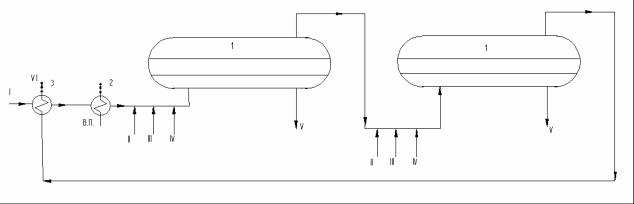
Let us consider the process flow of electric dehydrator (fig. 1). In accordance with the diagram, oil (I) is pumped through heat exchangers (3), where heat of outlet oil is recovered. Then it passes through either steam heater or heat exchangers heated by hot oil distillates, is mixed with hot fresh water (III), demulsifying agent (II) and alkali (IV) to suppress hydrosulfuric corrosion and neutralize acids. Then, oil emulsion is sent consecutively to two electric dehydrators (1) where it is segregated to dehydrated and desalinized oil (VI) and salt (drained) water (V).
Fig. 1. Electric Dehydrating and Desalinating Unit Process Flow:
1 – first and second stage electric dehydrator; 2 – steam heater; 3 – heat exchanger; I – crude oil; II – demulsifier; III – water; IV – alkali; V – salt water;
VI – desalinized and dehydrated water
Oil dehydration and desalination in electric field is carried out in special units: electric dehydrators, which can be of different design: vertical, spherical, or horizontal. Currently, the most advanced units are horizontal electric dehydrators which make it possible to treat oil under more severe conditions (temperature is up to 160 °C and pressure is up to 24 bar). Such electric dehydrators are more productive and ensure high quality of oil treatment.
In terms of design, such electric dehydrators differ by the method of emulsion injection into the unit and the design of the electrodes (injection of emulsion under layer of hot water or in the inter-electrode space; one rectangular electrode along the whole length of the unit, or several pairs of round electrodes; combined injection of the emulsion under water layer and into the inter-electrode space; three pairs of electrodes).
12
3.3. High-Viscosity Oil Treatment
The problem of treating high-viscosity oil arose due to increase in extraction of highviscosity (heavy) oils (HVO) and natural oil bitumen (NOB). Here, HVO means oils with ρ=0.92–0.99 and η up to 1000 Pa sec at 20°C.
NOB is the organic part of oil bituminic rocks (sandstone and limestone) with ρ about 1 and over, and η up to 5000 Pa sec at 20°C.
Both HVO and NOB are characterized by high content of resins and asphaltenes (up to 40 mass %), sulfur (up to 5 mass %), nitrogen (up to 1 mass %), and metals (up to 1500 mg/kg).
HVO are extracted by thermal formation treatment: using interbedding burning or high temperature steam injection.
Two methods are used to extract NOV: displacement by interbedding burning, and extraction, when rocks are extracted, ground, and treated with hot water or organic solvents to extract organic matter.
In all cases of HVO or NOV extraction, very stable emulsions of water with organic mass are formed, due either to moisture formed during interbedding burning, or to water extraction.
Higher stability of such emulsions is determined by the fact that density of HVO and NOV is close to the density of water, they are rich in natural emulsifiers, and the size of water globules (up to 50 %) is less than 10 µm. Segregation of such emulsions is a very complicated task, and sometimes even increasing the consumption of the demulsifying agent by 20 or 30 times does not produce the desired effect. To break such emulsions, special methods are used. Especially, one can add 10–15 mass % of light solvent (kerosene) to HVO or POV. On the one hand, it reduces oil density and viscosity, and on the other hand, since it is a non-electrolytic demulsifying agent, it dissolves a part of solvate shells on water globules. In such case, emulsions are closer to the typical ones, and can be broken in electric desalting plant processing units in 2 or 3 stages.
After electric desalting plant, solvent is removed and recycled.
Alcohol (especially, isopropyl) is also used as solvent. In such case, solvent not only reduces oil density and viscosity and dissolves the adsorption layers, but also absorbs water. In such case, dehydration efficiency is higher. However, such method has disadvantages: washing fresh water cannot be fed to electric desalting plant (desalination is affected) and there must be the special stage for separation of watered alcohol from oil and dehydration of alcohol for repeated application.
In industry, only gasoline and kerosene cuts are used as solvents.
13
4. OIL AND OIL CUT DISTILLATION
There are different types of oil and oil cut distillation.
4.1. Oil and Oil Cut Flash and Multiple Distillation
Oil and oil cut flash distillation is a single-stage process of heating crude oil in pipe still coil up to defined temperature (180–240 °C; 330–260 °C; 400–420 °C) and its evaporation in an adiabatic evaporator. Under such process, the steam phase is separated from the liquid one, removed from the top, cooled down further in a condensing cooler, and sent to receiver. The liquid phase is removed from the bottom of the evaporator, and is also sent to the receiver.
Multiple-evaporation distillation consists of two, three or more single-stage evaporations, and the formed vapors are separated from the liquid phase at each stage (in a single shot).
Multiple distillation provides higher sharpness of cuts compared with the flash distillation. However, it is characterized by smaller portion of the strippant at the same heating temperature.
Therefore, an important advantage of flash distillation is high share of the strippant at one and the same heating temperature. In order to improve sharpness of cuts, the flash distillation is used in combination with fractionating.
4.2. Oil and Oil Cut Distillation in the Presence of Evaporating Agent
Oil and oil cut distillation in the presence of evaporating agent makes it possible to increase concentration of high-boiling components in the residue without raising distillation temperature. Such effect is connected with the decrease of partial pressure of distilled cut and, consequently, in temperature of transition to vapor phase. In industry, water steam (overheated) is used as evaporating agent. Along with that, such substances as inert gases (N2, СО2), hydrocarbon gases, and kerosene-gasoil cuts can be used as such agents. Application of evaporating agent, especially water steam, makes it possible to reduce distillation temperature on 10–20 °C at the same distillation yield.
Despite the fact that water steam is widely used as evaporating agent, this method has a number of disadvantages:
–high heat consumption to produce overheated steam; and
–high consumption of cooling water to condense the steam.
14
Good results are achieved when inert gas is used as evaporating agent. However, this method has not become widely used due to bulkiness of equipment to be used (gas superheaters, condensers), low gas heat transfer factors, and complexity of complete removal of distilled oil product from gas flow.
Light oil cuts are more conveniently used as evaporating agents. In such case, the lower the boiling point of evaporating agent, the lower the distillation temperature. However, use of very low-boiling products result in significant loss of agent in the course of distillation.
Kerosene-gasoil cuts (instead of water steam) have received wide recognition in fuel oil and heavy cut distillation.
4.3. Vacuum Distillation of Oil and Oil Cuts
As a rule, oils and oil cuts are distilled under atmospheric pressure at temperatures not higher than 350–370 °C, since higher temperature intensifies thermal cracking of hydrocarbons to be distilled. Due to this fact, high-boiling oil products are distilled under vacuum. When using vacuum and temperature ranged 410–420 °C, distillates with boiling point 480–500 °C are stripped under atmospheric pressure, and if deep vacuum and packed columns with low hydraulic resistance are used, up to 580 °C.
The existing methods make it possible to maintain vacuum at the top part of the vacuum column at level 20–50 mm Hg. The lower the vacuum, the deeper oil cuts are. Combining packed contact devices with low hydraulic resistances makes it possile to strip distillates with boiling point 550–580 °C and produce heavy tar in residue.
4.4. Extractive and Azeotropic Fractionating
Flash ditillation under vacuum and with evaporating agent makes it possible to fractionate oil into sharp cuts. However, under flash distillation it is impossible to fractionate the narrowest cuts and individual hydrocarbons from oil (especially, raw materials for petrochemical processes). It can be accounted for by the fact that oil hydrocarbons often form close-boiling or azeotropic mixtures (in particular, boiling point of benzene and cyclohexane is, respectively, 80.1 and 80.75°C), and cannot be separated even by close fractionation.
To separate such mixtures and extract individual hydrocarbons, azeotropic fractionating and extractive fractionating are used.
Such methods are based on injection foreign agent into the system, and the presence of such agent increases the difference in volatilities of hydrocarbons to be fractionated. Then, the required hydrocarbon can be extracted using the traditional distillation methods.
15
If injected hydrocarbon is less volatile than substances to be fractionated, it is injected from the top of the tower and removed from the bottom of the tower, together with residue. Such fractionating is termed extractive, and injected substance is termed solvent (extractant). Introduction of solvent into the system causes changing in relative-volatility ratio due to different quantities of the solubility ratio for different components.
Basic requirements for solvent:
–sufficiently high boiling point, to make it possible to distill the components removed with solvent in the form of mixture;
–high dissolving capacity, and, consequently, low consumption.
If added substance is more volatile than components to be fractionated, it is injected into the tower together with crude oil, and removed with vapors from the top of the tower. Such type of fractionating is called azeotropic, and substance added to the system is termed remover.
Basic requirements for remover:
–it should provide formation of azeotrope with one or several mixture components;
–it should have boiling point close to boiling point of the stripped substance, which makes it possible to achieve the greatest difference between the azeotrope’s and other components’ boiling points;
–it should be easily removable from azeotropic mixture.
However, the use of extractive and azeotropic fractionating requires preparation of the crude, which should boil off within the narrowest temperature range. Therefore, these fractionating methods must be preceded by the methods of traditional (precision) fractionating.
5. FRACTIONATING TOWER HEAT SUPPLY AND REMOVAL
One of the important elements of oil and oil cut fractionating technology is fractionating tower heat supply and removal since fractionating is a thermodynamic process with continuous heat supply/removal: it ensures formation of temperature profile along the entire tower height and, consequently, fractionating driving force. The higher the tower heat supply (and removal), the higher the reflux-to-product ratio of the tower, and the higher the precision of fractionating. However, is requires higher power consumption for fractionating.
Heat is supplied to fractionating tower with oil flow and at the bottom of the stripper. Option of heat supply with oil flow is usually limited due to thermal decomposition
16
PNRPU
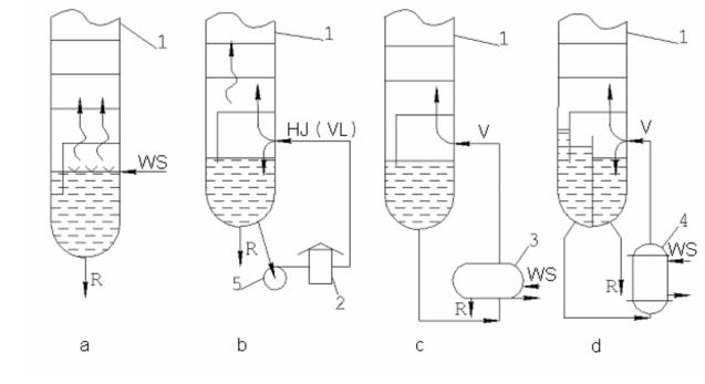
of the feedstock (350–360 °C – atmospheric section, and 400–420 °C – vacuum section under fuel oil refining). If the tower is used for stripping light distillates and defined overheating of the tower bottom does not cause cracking reactions, additional heat flow is fed from the bottom of the tower by either reboiler or hot jet (circulation of the tower residue through the pipe still and heated flow 300–350 °C supply to the stripper) (fig. 2).
The heat supplied by this or that method evaporates a part of liquid phase and creates required vapor pressure in the stripper.
Fig. 2. Heat Supply from the Bottom of Fractionating Towers:
1 – tower, 2 – pipe still, 3 – reboiler (evaporator), 4 – straight-through boiler;
R – residue, HJ – hot jet, V – vapor flow, VL – vapor-liquid flow, WS – water steam.
Heat is removed only in the product-concentrating section of the tower and is used to produce liquid flow for the internal reflux on the trays. In simple towers (without stripping side-cut distillates), heat is always removed from top of the tower (sharp, cold evaporating reflux). In complex columns, heat can be removed in several cross sections along the tower height (non-evaporating or circulation reflux). As a rule, combined reflux (upper evaporating and circulation reflux) is used in complex tower.
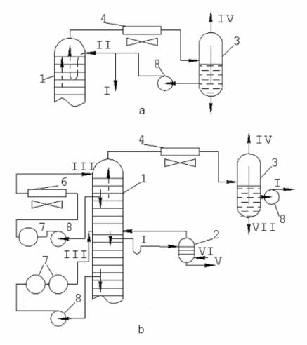
Cold evaporating reflux process flow is as follows: vapors leaving through the top of the tower are condensed in condenser-cooler and collected in reflux tank, from which some of them are recycled to the top tray of the tower inn the form of cold evaporating reflux, and the balance amount is removed in the form of final product (fig. 3, a).
17
The required amount of the cold evaporating reflux to be recycled is determined using the following formula:
Gc.evap. =Qc.evap./ qvtD – qlt cond-cool., |
(6) |
where Q is amount of heat to be removed from the column using the given type of reflux, qvtD and qlt refr. cond. are entalpies of vapors and liquid phase at tD of the top of the tower and outlet tcond-cool. of condenser-cooler (usually, 30–40 °C), respectively.
Fig. 3. Fractionating Tower Heat Removal Process Flow: 1 – tower, 2 – stripping,
3 – separating setting tank; 4 and 5 – condensers of air and water cooling, 6 – cooler,
7 – heat exchangers, p – pumps; I – rectificate (gasoline), II and II – evaporating and non-evaporating reflux, IV – hydrogen gas; V – side-cut distillate (kerosene), VI and VII – water steam and its condensate
Cold non-evaporating or circulation reflux process flow is as follows: a part of liquid phase from any tray along the height of the tower is pumped through heat exchanger and cooler, and cooled flow is recycled to the same or a higher tray. As a result, additional reflux stream is produced to realize the fractionating process (fig. 3, b). The required amount of circulation reflux is determined by the following formula:
18
G c.refl.= Qc.refl./qlt1 – qlt0, |
(7) |
where Qc.refl. is the amount of heat to be removed by circulation reflux, and qlt1 and qlt0 are entalpies of liquid phase at t1 (tower outler) and t0 (tower inlet).
Circulation reflux is used when aggressive raw materials are processed, especially in the presence of water steam. In such case, coolers are less corroded and condensercoolers are more corroded.
The use of circulation reflux makes it possible to discharge liquid phase of the above sections, increase feedstock preheating, and reduce pipe still thermal load.
Usually, in complex tower, not more than 2 circulation refluxes are arranged, according to the number of stripped side cuts.
6. STRAIGHT OIL DISTILLATION PROCESS FLOW. OIL DISTILLATION MATERIAL BALANCE.
OIL DISTILLATION PRODUCTS
CHARACTERISTICS AND APPLICATION
The basic process flow diagram of straight oil distillation should be selected when oil processing (fuel, oil-fuel, or complex) segment is specified.
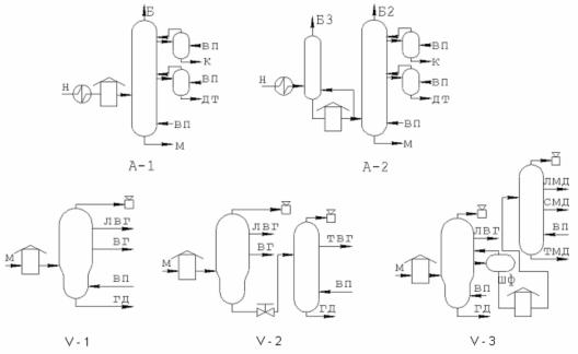
In the atmospheric section, single-tower distillation can be applied (fig. 4) (A-1) or double-tower (A-2), with preliminary topping of oil. It depends on gas and sulfur content (especially sour sulfur) of oil, i.e. primarily, it is determined by type and class of oil.
Straight oil distillation vaccum section can be optionally arranged as follows (fig. 4): B-1: single-tower for producing both fuel and oil distillates;
B-2: single-tower with tar residual evaporator for stripping heavy distillates with a final boiling point 540–560 °C;
B-3: double-tower for oil segment, the first tower strips cuts up to 350°C (light vacuum gasoil) and long distillate (350–550 °C), which, in its turns, after heating is fractionated into oil distillates at the second tower.
Then, according to the accepted oil refining process, the general and stage material balance of oil distillationshould be developed.
Oil processing in the straight distillation unit (atmospheric-vacuum pipe still, AVT) is a multi-stage process which includes stages of oil topping, atmospheric and vacuum distillation, stabilization and rerun distillation of gasoline. Therefore, both the general
19
and stage material balances of oil distillation are to be considered. Let us consider the general material balance for the final products of distillation at each stage and characterize each of them.
Fig. 4. Process flows of atmospheric (A-1 and A-2) and vacuum (V-1, V-2, and V-3) stages of atmospheric-vacuum pipe still: Н – oil, M – fuel oil, Б – gasoline, K – kerosene, ДТ – diesel fuel, ЛВГ and ТВГ – light and heavy vacuum gasoils, respectively,
ВГ – vacuum gasoil, ЛМД, СМД, ТМД – light, medium, and heavy oil distillates, ШФ – long distillate (300–550 °C), ГД – tar, ВП – water steam.
Initial oil (100 %). It is supplied to the unit with the mineral salt content from 50 to 300 mg/l and water content, 0.5–1.0 mass % (groups 1 and 2).
Hydrocarbon gas. The yield depends on oil-dissolved gas content of after field treatment. If oil is light (density from 0.8 to 0.85), gas yield may amount to 1.5–4.8 mass %. For heavy oils, yield is lower (0.3–0.8 mass %). If oil was additionally stabilized in field, gas yield is zero. Up to 90 % of such gas is removed in gasoline extraction unit. In terms of composition, these are saturated hydrocarbons С1–С4, with an C5. Low pressure and small amount of produced gas make it impossible to use it directly as raw material for gas fractionation units. It is mainly used as fuel for atmospheric-vacuum pipe still. If gas is compressed to pressure 2–4 MPa, it can be processed in gas frationation unit.
20