

книги / FISMA and the risk management framework the new practice of federal cyber security
..pdfAn overview of the potential of quantitative coating adhesion measurement by scratch testing |
157 |
Calculated failure stresses for alumina scales on MA956 and TiN on stainless steel are shown in Figure 9 where the stress introduced by the scratch stylus has been added to the residual stress in the coating to give the failure stress. It is clear that the failure stresses for arc evaporated TiN are now higher than for sputtered material since the scratch calibration constant is higher and the residual stress in the arc coatings is also much higher (7.0GPa compressive as opposed to 2.1 GPa compressive for the sputtered TiN film).
The wedge failure stresses in Figure 9 can then be used to determine the work of adhesion by plotting the calculated <JF against the reciprocal of the square root of coating thickness (Figure I 0). It is then possible to separate the two components contributing to wedging failure (Equations 5 and 6); the slope of this curve can be used to determine the interfacial fracture energy, Gi. using the coating data in Table 2, whereas the intercept gives a measure of coating fracture strength, crw. These values are presented in Table 3. It is clear that the fracture strengths of the coatings or scales are quite similar but that there is a much greater difference in the interfacial adhesion.
Table 3: Wedge fracture stress and interfacial fracture energy determined from the scratch test.
|
Interfacial |
Wedge |
Substrate/coating |
fracture energy, Gi |
fracture stress |
|
(J/m2) |
(GPa) |
SIP TiN/304 |
538 |
4.64 |
Arc TiN/304 |
2578 |
4.89 |
Ah03/MA956 |
|
|
1150°C |
35.0 |
7.59 |
1250°C |
16.9 |
8.06 |
|
|
|
It is important to determine if failure is really interfacial if the scratch test is to be used for adhesion assessment, so Auger Electron Spectroscopy (AES) was used to identify the locus of interfacial failure for both materials. In the case of the alumina scales there is always a thin layer of oxide on the uncovered substrate at the bottom of the wedge-spalled pit. However, this may have been formed after scratch testing due to the exposure of the bare metal substrate to the atmosphere. There is no evidence for substrate material on the underside of any spalled debris that was collected. It is therefore reasonably certain that failure occurs at or very near to the interface once the wedge crack reaches the interfacial region.
!58
(a)
ro
a..
~
c
.Q
_§
<ii
a.
(/)
<ll
Ol
u
<ll
3: u
<ll u
:::l
u
_!;
_!;
(/)
(/)
E!
1ii
E!
~
~
<ii u
:;:::;
8
(b)
ro
a..
~
c
0
~
<ii
a.
(/)
<ll
Ol
u
<ll
3':
_!;
(/)
(/)
~
05
~
~
·a
u.
<ii
,g
8
Scratchin& of materials and applications
MA956
9.1 |
|
|
|
|
|
|
|
|
|
|
|
|
|
. |
', |
1 |
|
|
|
|
|
|
|
|
|
|
|
|
|
|
|
||||
9 |
|
|
... |
1200"C |
|
|
|
|
|
|
|
|
|||||
|
|
|
---1150°C |
|
|
|
|
|
|
|
|
|
|
.. |
|
||
8.9 |
|
|
-- 0 - . 1250°C |
|
|
X |
|
|
|
|
|
',() |
|
|
|||
|
|
·X |
|
|
|
|
|
|
|
|
|
|
|
|
|
|
|
|
|
|
1300°C |
|
|
|
|
|
|
|
|
|
|
|
|
||
|
|
|
|
|
|
|
|
|
|
|
|
|
|
|
|
||
8.8 |
|
|
|
|
|
|
|
|
|
|
• |
|
|
|
|
1 |
|
|
|
|
|
|
<>' |
|
|
|
|
|
|
||||||
|
|
|
|
|
|
|
|
|
|
|
|
|
|
||||
|
|
|
|
|
|
|
|
|
|
|
|
|
|
|
|||
8.7 |
|
|
X |
0 |
|
• |
|
|
|
|
|
|
|
~ |
|||
|
|
|
|
|
|
|
|
|
|
|
|
_J |
|||||
|
|
|
|
|
|
|
|
|
|
|
p.~ |
||||||
8.6 |
|
|
|
|
|
I |
-- 0 = 7.59 + o.oo43/t112 |
R= 0.983 |
|||||||||
|
|
|
|
|
i |
|
0 = 8.01 + 0.0026/!112 |
R= 0.998 |
|
||||||||
|
|
|
|
|
|
|
|
||||||||||
8.5 |
~ |
|
|
|
|
|
|
|
|
. 0= 8.06 + 0.0027/!112 |
R= 0.997 |
|
|||||
|
• |
|
|
|
|
|
|
0 = 8.28 + 0.0022/!112 |
R= 0.917 |
|
|||||||
8.4 |
|
|
|
|
|
|
|
|
|
|
|
|
|
|
|||
|
|
|
|
|
|
|
|
|
|
|
|
|
|
|
|
|
|
200 |
|
220 |
240 |
260 |
|
|
280 |
|
300 |
|
320 |
340 |
360 |
||||
|
|
|
|
|
|
|
|
111112 (m-112) |
|
|
|
|
|||||
|
|
|
|
Wedge Spallation in PVD TiN |
|
|
|
||||||||||
20 |
|
|
|
|
|
|
|
|
|
|
|
|
|
|
|
|
|
|
|
|
|
|
|
|
|
|
|
|
|
|
|
|
|
|
|
18 |
r |
|
|
|
|
|
|
|
|
|
|
|
|
|
' |
|
|
|
t |
|
|
|
|
|
|
|
|
|
|
|
|
|
|
||
|
|
|
|
|
|
|
|
|
|
|
|
|
|
|
|
||
16 |
~ |
|
|
|
|
|
|
|
|
|
|
|
|
|
|
|
|
14 |
~ |
|
|
____._ Arc evaporated TiN |
|
|
1j |
||||||||||
|
|
|
-B--- Sputtered TiN |
|
|
||||||||||||
|
|
|
|
|
|
|
|||||||||||
|
|
|
|
|
|
|
|
||||||||||
12 |
f |
|
|
|
|
|
|
|
|
|
|
|
|
|
·--; |
|
|
|
|
|
|
|
|
|
|
|
|
|
|
|
|
||||
|
|
|
|
|
|
|
|
|
|
|
|
|
|
< |
|
||
|
|
|
|
|
|
|
|
|
|
|
|
_-------s |
; |
|
|||
|
|
|
|
|
|
|
|
|
|
|
|
;I |
|||||
|
t |
|
|
|
|
|
|
|
|
|
|
|
|
|
I |
||
10 |
|
|
|
|
|
|
|
|
|
|
|
|
|
I |
|||
|
|
|
|
|
|
|
|
|
|
|
|
|
|
|
|
||
|
|
|
|
|
|
|
|
|
|
|
|
|
|
|
|
4 |
|
|
|
|
|
|
|
|
|
|
|
|
|
|
|
|
~ |
|
|
8 |
|
|
|
|
|
|
|
|
|
|
|
|
|
|
|
||
250 |
|
260 |
270 |
|
280 |
|
|
290 |
|
300 |
|
310 |
320 |
330 |
|||
|
|
|
|
|
|
1111;2 |
(m·112) |
|
|
|
|
|
|
||||
Fig. 10. Variation of critical failure stress, crF with the reciprocal of the square root of coating thickness, t, for (a) alumina scales on MA956 at different oxidation temperatures, (b) TiN on stainless steeL

An overview of the potential of quantitative coatinK adhesion measurement bv scratch testinK |
I 59 |
Assessing the failure locus of the TiN coatings is more complex since a thin (-lOOnm) titanium interlayer was used to promote coating adhesion which dissolves a considerable amount of carbon and oxygen from the substrate surface in the early stages of deposition [37]. In the coating processes used ion bombardment of the growing coating is employed to promote adhesion by forming a pseudo-diffusion zone in the interface region giving a metallurgical bond with no well-defined interface plane. The gold TiN was clearly removed at the bottom of wedge spalls but there was still considerable titanium present on the surface of the substrate. SIMS images of the surface showed that the nitrogen content of this surface layer is very low compared to the carbon and oxygen levels. It thus seems likely that failure has occurred within the titanium interlayer.
For both materials the interfacial fracture energies are higher than that expected from the fracture energy of the coating (- 1J/m2) but lower than or comparable to typical substrate values (- 103J/m2). This also indicates that the failure crack is propagating at or near the interface with at least some crack tip plasticity occurring within the substrate. As G; increases the effective coating/substrate adhesion increases so the results here indicate that the TiN/stainless adhesion is better than that for alumina!MA956 since the mechanical properties of the substrates, and hence the energy dissipated in crack-tip plasticity processes, are very similar. Since the TiN coated stainless steel has much smaller spalled regions and the coating is considerably more resistant to detachment during abrasion than the alumina scale the relative values of the fracture energies are as expected.
Scratch testing of MA956
50 |
|
|
|
|
|
|
|
|
|
|
|
9 |
|
|
|
|
|
|
|
|
|
|
|
|
|
||||
|
|
|
|
|
|
|
|
|
|
|
|
|
|
|
40 |
|
|
|
|
• |
Wedging stress |
I ~ |
|
|
|
|
|
||
|
|
|
|
|
|
|
|
|||||||
|
|
|
|
|
|
|
|
|
|
|
|
|
|
|
|
|
|
|
|
•.. |
|
T |
|
|
|
|
8.5 |
:2: |
|
|
|
|
|
|
|
|
|
|
|
|
|
|||
|
|
|
|
|
|
|
|
|
|
|
|
|
co |
|
|
|
|
|
|
|
|
|
|
|
|
|
|
co |
|
|
|
|
|
|
|
|
|
|
|
|
|
|
|
0. |
30 |
|
|
|
|
|
|
|
|
I |
|
|
|
|
<Q. |
|
|
|
|
|
|
|
|
|
|
|
|
::::l |
||
|
|
|
|
|
|
|
|
|
• |
|
|
|
|
<0 |
|
|
|
|
|
|
·· |
|
|
|
8 |
~ |
|||
|
|
|
|
|
|
|
|
|
|
|
|
..... |
||
|
|
|
• |
|
|
|
|
|
|
|
|
|
|
(/) |
20 |
|
|
|
|
|
|
|
|
|
|
|
|
(/) |
|
|
|
|
|
|
|
|
|
|
|
|
|
G5 |
||
10 |
|
|
|
|
|
|
|
|
|
|
|
|
||
|
|
|
' |
|
|
|
|
|
|
|
|
|
|
-o |
|
|
|
|
|
|
|
|
|
|
|
|
|
|
|
|
|
|
|
|
|
|
|
|
|
|
|
7.5 |
E. |
|
|
|
|
|
|
|
|
|
|
|
|
|
|
||
0 |
|
|
|
I____.__ lnteriacial Energy I |
|
|
|
7 |
|
|||||
|
|
|
|
|
|
|
||||||||
|
|
|
|
|
|
|
|
|
|
|
||||
|
|
|
|
|
|
|
|
|
|
|
||||
1100 |
1150 |
1200 |
1250 |
1300 |
1350 |
|
||||||||
Oxidation Temperature, CC)
Fig. 11. Variation of interfacial fracture energy with wedge fracture strength of alumina scales on MA956 as a function of oxidation temperature.
160 |
Scratching of materials and applications |
The higher value of Gi for the arc evaporated TiN compared to the sputtered material indicates that the adhesion of the arc coatings is actuaiiy much better than their sputtered counterparts, a conclusion which is counter to what might be drawn from the scratch test critical loads. The coating flux in arc evaporation is highly ionised compared to sputtering and the bombardment of the substrate with these highly ionised particles in the early stage of deposition is much more effective at cleaning the surface and forming strong chemical bonds [31].
The interfacial fracture energy for alumina on MA956 is reduced as the oxidation temperature increases (Figure 11) but the fracture strength of the coating is actuaily increased. During the long exposures necessary to grow thick scales on the ailoy at low temperatures void-like defects are known to grow in the scale. These will act as the crack nucleation sites that lead to failure [38]. If the scale has a constant toughness then the more defective low temperature scales would be expected to fail at a lower stress level. The better adhesion of the low temperature scales is more difficult to explain but may be due to different chemistry of the interfacial regions.
Hard coating on hard substrate
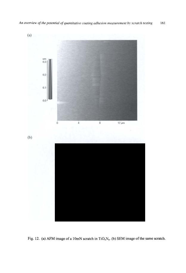
For the TiOxNy coating on glass the AFM image does not show a clear sign of adhesion failure though some damage at the side of the track is visible (Figure 12a). The edge on orientation is not perfect - more of the indenter face is involved in forming the left side of the scratch. There are no obvious through-thickness cracks in the AFM images, but the sharp edges delineating the scratch in the SEM image imply that through thickness cracking has occurred (Figure 12b). Energy dispersive x-ray microanalysis in the SEM confirms that coating detachment has occurred.
There is a smooth increase in friction force with scratch length (Figure 13a) up to a normal load of 3.2mN when some oscillations in the friction trace are observed. Such osciilations are also visible in the friction coefficient trace (Figure 13b). However, the clearest indication of failure is seen in the work of friction plot (Figure 13c) when jumps are observed associated with each failure event. The work of friction, which is the integral of the friction coefficient up to the given displacement, represents the irreversible work done during scratching. The smooth increase in work of friction is related to the increased work necessary to plasticaiiy deform the coating/substrate system to create the scratch track. However, the rapid increase in work of friction correlates with the onset of coating fracture. Both through-thickness and adhesive failure can generate such jumps.
For through thickness cracking the crack length is typicaiiy of the order of a few microns and the coating thickness is 400nm giving a crack area of -to-12m2• Given typical surface energies of IJ/m2 the size of a jump in the work of friction trace might be expected to be of the order of 1pNm which is much smaiier than observed in Figure 13c. Given that the area of adhesion failure is typically two orders of magnitude greater it is likely that these jumps are due to adhesive failure. The adhesion failure is visible in the scanning electron micrograph (Figure 12b) and it appears that this failure occurred in several stages from the jumps in the work of friction trace.

162 |
Scratching of materials and applications |
(a)
|
0 |
|
-500 |
...--. |
|
z |
-1000 |
:::::::1.. |
|
-Q) |
|
(.) |
|
'- |
-1500 |
0 |
|
LL |
|
ctl |
|
' |
|
Q) |
|
-ctl |
-2000 |
_J
-2500
-3000
0 |
2 |
3 |
4 |
5 |
6 |
7 |
8 |
Lateral Displacement (!Jm)
(b)
|
0.5 |
|
|
|
|
|
|
|
|
|
|
|
|
|
|
|
|
|
|
|
|
|
|
|
|
|
0.4 |
|
|
|
|
|
|
|
|
|
|
|
c: |
|
|
|
|
|
|
|
|
|
|
|
|
-Q) |
|
|
|
|
|
|
|
|
|
|
|
|
"(3 |
|
|
|
|
|
|
|
|
|
|
|
|
;;:::: |
0.3 |
|
|
|
|
|
|
|
|
|
|
|
Q) |
|
|
|
|
|
|
|
|
|
|
|
|
- |
|
|
|
. |
|
|
|
|
|
|
|
|
0 |
|
|
|
|
|
|
|
|
|
|
||
() |
|
|
.. |
|
|
|
|
|
|
|
|
|
c: |
|
|
|
•:I |
|
|
|
|
|
|
|
|
0.2 |
|
... |
|
|
|
|
|
|
|
|
||
0 |
|
, |
|
|
|
|
|
|
|
|
||
"+=' |
|
|
|
.• |
|
|
|
|
|
|
|
|
(.) |
|
|
|
|
|
|
|
|
|
|
|
|
·;::: |
|
|
|
|
|
|
|
|
|
|
|
|
LL |
|
|
|
|
|
|
|
|
|
|
|
|
|
0.1 |
|
|
• |
|
|
|
|
|
|
|
|
|
0 |
|
|
|
|
|
|
|
|
|
|
|
|
0 |
2 |
3 |
4 |
5 |
6 |
7 |
8 |
||||
|
|
|||||||||||
Lateral Displacement (!Jm)
(Continue to the next page)

An overview of the potential of quantitative coating adhesion measurement by scratch testing |
163 |
(c)
|
1 104 |
|
|
|
|
|
|
|
|
-_ |
|
|
|
|
|
|
|
|
|
|
|
||
|
|
|
|
|
|
|
|
|
|
|
|
-E |
9000 |
|
|
|
|
|
|
|
/./ |
|
I |
8000 |
|
|
|
|
|
/ |
|
|
|
|
|
z |
|
|
|
|
|
|
|
|
|
|
|
0 |
|
|
|
|
|
|
|
|
|
|
|
a. |
|
|
|
|
|
|
|
|
|
|
|
-c |
7000 |
|
|
|
|
/ |
|
|
|
|
|
0 |
|
|
|
|
|
|
|
|
|
|
|
~ |
6000 |
|
|
|
|
|
|
|
|
|
|
(.) |
|
|
|
|
|
|
|
|
|
|
|
·c |
|
|
|
|
|
|
|
|
|
|
|
- |
|
|
|
|
|
|
|
|
|
|
|
5000 |
|
|
|
/ |
|
|
|
|
lI |
||
, |
|
|
|
|
|
|
|
|
|
||
.::t:. |
|
|
|
|
|
|
|
|
|
||
0 |
4000 |
|
/ |
|
|
|
|
|
|
||
~ |
|
|
|
|
|
|
|
||||
|
3000 |
t |
|
|
|
|
|
|
|||
|
2000 |
|
|
|
|
|
|
|
|
I |
|
|
3.5 |
4 |
4.5 |
5 |
5.5 |
6 |
6.5 |
7 |
7.5 |
||
Lateral deflection (!lm)
Fig. 13. (Continue from the previous page) Variation of (a) friction force, (b) friction coefficient and (c) work of friction with scratch displacement for 400nm TiOxNy on float glass.
The total work represented in the jumps is 855pNm and the area of delamination is approximately 18~m2• This would predict an interfacial fracture energy of 47.5J/m2 which is comparable to results obtained for brittle coatings on brittle substrates by other methods. However, without improvements in the measurement of area this value must be regarded as tentative.
The work of friction could, in theory, be used to characterise the failure of hard coatings on soft substrates. However, given the size of the failures and the likely interfacial fracture energies the work of friction resolution of conventional scratch testing equipment is insufficient to resolve the failures.
CONCLUSIONS
The scratch test is a good method for quality assurance/quality control testing of the adhesion of hard coatings and is useful in the development of new coatings for process optimisation. However, at present, quantitative adhesion data from the test which might be used as the basis of a performance model is difficult to extract from the test data. In most cases the stresses around the moving indenter are too complicated to be predicted accurately and therefore the
164 |
Scratching of materials and applications |
stresses driving coating failure are not known. However, some failure modes occur sufficiently far away from the indenter where the stress state is simpler and quantification is a possibility.
The two main adhesion related failure modes in the scratch testing of hard coatings are wedge spallation and buckling. Buckling occurs for thin coatings which are able to bend in response to applied stresses. The stresses responsible for failure are complex due to the fact that buckling is confined within the region of pile-up close to the indenter. For thicker, stiffer coatings wedge spallation becomes the dominant failure mechanism. This occurs well ahead of the moving indenter and the stresses which are responsible for failure approximate to a state of pure compression. Wedge spaiiation stresses can, therefore, be quantified by calibration enabling the interfacial fracture energy to be determined.
To derive the maximum benefit from the scratch test better theoretical models for the stress fields associated with a moving indenter in a coating/substrate system are needed. These are most likely to be based on finite element analysis, but the modelling approach would need to include a large number of factors if the true stress state is to be predicted accurately enough. The use of good constitutive equations for coating and substrate, the incorporation of a suitable fracture model and a mechanism for handling interfacial and surface roughness will be essential if this is to be achieved. If a model is to be developed which can predict the onset of fracture then a method of representing the defect distribution in the system is also necessary. Furthermore the incorporation of residual stresses into the model is essential for accurate results. A considerable amount of development and validation work is thus required for any new system under investigation.
With the emergence of depth sensing indentation and scratch systems with high resolution of applied load, friction force and lateral displacement, it is possible to make more direct measurements of interfacial fracture energy for thin coatings. This approach needs investigating on a wider range of systems and requires a very accurate and critical assessment of the delamination area but offers a more quantitative evaluation method when compared to the traditional scratch test.
ACKNOWLEDGEMENTS
The authors would like to thank Ian Gilbert for some SEM images and coiieagues at Newcastle University for useful discussions.
REFERENCES
Perry A. J. (1981) Thin Solid Films 78, 77.
2Steinmann, P. A. and Hintermann, H. E. (1985) J. Vac. Sci. Techno( A3, 2394.
3Vaiii, J. (1986)J. Vac., Sci. Techno/. A4, 3001.
4Hintermann, H.E. (1984) Wear 100,381.
5Perry, A.J. (1983) Thin Solid Films 107,167.
6Buii, S.J. and Rickerby, D.S. ( 1990) Surf Coat. Techno/. 42, 149.
7Benjamin, P., and Weaver, C. (1960) Proc. Roy. Soc. Lond., SerA 254, 163.
8Buii, S.J. (1991) Suif. Coat. Techno/. 50, 25.
An overview of the potential of quantitative coating adhesion measurement by scratch testing |
165 |
|
9 |
Bull,S.J. (1995) Materials at High Temp. 13, 169. |
|
10Bull, S.J. (1997) Tribology Int. 30, 491.
11Mittal, K.L. (1978) in Adhesion Measurement of Thin Films, Thick Films and Bulk Coatings, pp5-17, K.L. Mittal (Ed.), STP No. 640, ASTM Philadephia.
12Mittal, K.L. (1976) Electrocomponent Sci. Techno/. 3, 21.
13Mittal, K.L. (1995) in Adhesion Measurement of Films and Coatings, ppl-13, K.L. Mittal (Ed.), VSP, Utrecht, The Netherlands.
14Venkataraman, S., Kohlstedt D.L., and Gerberich, W.W. (1992) J. Mater. Res. 7, 1126.
15Kriese, M.D., Boismier, D.A., Moody, N.R. and Gerberich, W.W. (1998) Eng. Fracture Mechanics 61, 1.
16Kim, K.S. and Aravas, N. (1988) Int. J. Solids Struct. 24, 417.
17Jeong, H.S. and White, R.C. (1993) J. Vac. Sci. Techno/. All, 1373.
18Bagchi,A., Lucas, G.E., Suo, Z. and Evans, A. G. (1995) J. Mater. Res. 9, 1734.
19Wei, Y., and Hutchinson, J.W. (1998) Int. J. Fracture 93,315.
20Burnett, P.J., and Rickerby, D.S. (1987) Thin Solid Films 154, 403.
21Amell, R.D. (1990) Surf Coat. Techno/. 43/44,674.
22Evans, H.E. (1994) Materials at High Temperature 12,219.
23Strawbridge, A., Evans, H.E., and Ponton, C .B. (1997)Mat. Sci. Forum 251/252,365.
24Thouless, M.D. (1998) Eng. Fract. Mech. 61, 75.
25den Toonder, J., Malzbender, J., de With, G., and Balkenende, R. (2002) J. Mater. Res. 17,224.
26Jiang, X.Y., Lauke, B., and Schueller, T. (2002) Thin Solid Films 414, 63.
27Holmberg, K., Laukkanen, A., Ronkainen, H., Wallin, K., and Varjus, S. (2003) Wear 254,278.
28Tymiak, N.I., Daugela, A., Wyrobek, T.J., and Warren, O.L. (2003) J. Mater. Res. 18, 784.
29Crepin, J., Bretheau, T., Caldemaison, D., and Ferrer, F. (2000) Acta Materalia 48, 505.
30Rickerby, D.S. and Newbury, R.B. (1988) Vacuum 38, 161.
31Mattox, D.M. (1994) in ASM handbook Volume 5: Surface Engineering, pp582-592, ASM International, Materials Park, Ohio, USA.
32Bull, S.J., (1997) Proc.41h Int. Conference on Advances in Surface Engineering Volume 1, pp274-285 P.K. Datta and J.S. Burnell-Gray (Eds) Royal Society of Chemistry, London.
33Oliver, W.C., and Pharr, G.M. (1992) J. Mater. Res. 1, 1564.
34Rickerby, D.S., Jones, A.M., and Bellamy, B.A. (1989) Surf Coat. Techno/. 37, Ill.
35Bull, S.J., Rickerby, D.S., Matthews, A., Leyand, A., Pace, A.R., and Valli J. (1988)
Surf Coat. Techno/. 36, 503.
36Rickerby, D.S., and Bull, S.J. (1989) Surf Coat. Techno/. 39/40, 315.
37Chalker, P.R., Bull, S.J., Ayres, C.F., and Rickerby, D.S. (1991) Mat. Sci. Eng. Al39, 71.
38Wilber, J.P., Nicholls, J.R., and Bennett, M.J. (1997) in Microscopy of Oxidation 3, pp207-220, S.B. Newcomb and J.A. Little (Eds), Institute of Materials book 675, London.
39Bull, S.J., Rickerby, D.S., Matthews, A., Pace, A.R., and Leyland, A. (1989) in Plasma Surface Engineering Volume 2, pp1227-1235, E. Broszeit, W D Munz, H Oechsner, K-T Rie and G K Wolf(Eds.), DGM Informationsgesellschaft, Oberursel.
40Steinmann, P.A., Tardy, Y., and Hintermann, H.E. (1987) Thin Solid Films 154,333.
166
CHAPTERS
CHARACTERIZATION OF MAR/SCRATCH RESISTANCE OF COATINGS WITH A NANO-INDENTER AND A SCANNING PROBE MICROSCOPE
Originally published in Tribo/ogv International vol 39. February 2006
WEIDIAN SHEN, LAN MI, and BIN JIANG
Surface Science and Nano-Tribology Laboratory
Department ofPhysics and Astronomy, Eastern Michigan University
Ypsilanti MI 48197, USA. E-mail: wshen@emich.edu
ABSTRACT
Mar/scratch resistance characterization techniques are presented in this paper, in which a Nanoindenter and a Scanning Probe Microscope (SPM) are used to measure the micro mar resistance (MMR), different responses of coatings to the marring stress, and critical forces for rough trough, cracking, delamination, and chipping, quantitatively. It provides a full spectrum of the mar/scratch resistance behavior of the tested samples. To comprehensively evaluate a coating/material in a specified application, introduction of a quantitative index is very useful. The concept of the index and the procedure to calculate it are described. In addition, to meet the variety of coatings/materials properties and the requirements in their applications, some complementary test methods are discussed.
KEYWORDS
Wear Resistance Measurement, Mar Resistance Measurement, Scratch Resistance Measurement, Nano Indentation and Scratching, and Critical Force for Cracking
INTRODUCTION
Mar/Scratch resistance is crucial for coatings/materials in many applications, e.g., the polymer topcoats used in the automotive industry [1-8]. Mars/marring refer to the light surface damages encountered in the real field that are usually shallow and narrow while scratches/scratching refer to the medium to severe damages. The majority of the damages to the topcoats applied on the automobile bodies belong to the mar category. Scanning Probe Microscope (SPM) was used to examine the mars encountered in the real field. The depth of most mars ranges from a couple of dozen nanometers to several hundred nanometers, while the width ranges from a couple of hundred nanometers up to 2 micrometers. A single mar may not be readily noticeable; however, the existence of a group of such mars does degrade the appearance of coatings. Mar resistance is a measure of a material's ability to resist small-scale mechanical stresses. However, some empirical test methods for mar/scratch resistance used a decade ago were not pertinent and appropriate, such as the crockmeter test, which was fairly popular in the paint industry in the