книги / FISMA and the risk management framework the new practice of federal cyber security
..pdfFriction, damage and stick-slip in the scratching ofpolrmers |
57 |
specimen surface. Scratch testing is one of the more frequently used methods for determining the mechanical resistance of coatings. It is a relatively quick and efficient way of acquiring information on the dominant damage mechanisms of a coating. So far, mechanical studies of this kind have been largely confined to those coatings that are relatively hard and tough [1]. A major area of interest is their resistance to detachment, that is, for the determination of the critical normal load for de-adhesion of the coating from the substrate. In contrast, more compliant coatings, such as elastomers, have received much less attention. For such systems, an area of interest is their tolerance to cohesive damage, which may affect the physical and chemical properties of the coatings. It is well known that several possible failure modes can occur [2, 3], and only some of these are the cause of detachment at the coating-substrate interface; other failure modes may depend on plastic deformation and fracture within the coating.
The friction force and the scratching resistance of a material could be influenced to varying degrees by attractive forces between the two contact surfaces. In a careful study [4] of contact between two rubber spheres, the area of contact was found to be larger than that predicted by the Hertz theory [5, 6]. This was attributed to the van der Waals forces attracting the rubber spheres to one another. The van der Waals attraction adds an additional force to the applied normal load, thereby increasing the area of contact.
One characteristic feature of elastomers is their ability to recover from large deformations. Their friction coefficient is generally high when they are sliding under a dry condition on another material [1]. Hysteresis phenomena may occur in their frictional behavior, and stick-slip often takes place [7]. When a stylus or an asperity slides across the surface of an elastomer, the material is compressed in the front of the contact and extended at the rear. A raised lip is often formed in the front of the contact. The associated subsurface cyclic compressive and shear deformations lead to viscoelastic hysteresis losses, which create a frictional resistance to sliding but result in no permanent damage if the yield stress is not exceeded. Therefore, elastomers usually have good erosive and abrasive wear resistance because of their ability to deform elastically [8].
In this chapter, friction and damage characteristics are studied for poly(n-butyl acrylate) (PnBA) and poly(dimethylsiloxane) (PDMS) coatings scratched by a spherical indenter. Crosslinked PnBA and cured PDMS behave as elastomers. This study will shed some light on the scratching behavior of elastomeric coatings.
Stick-slip processes between two sliding surfaces are commonly observed and occur in a wide range of length scales from atomic to macroscopic [9-11]. The stick-slip motion is a frictioninduced oscillation, which is a result of the interaction of an elastic system with a frictionally slipping surface and observed usually at slow sliding speeds. It is undesirable in precision movements and quiet operations. Sometimes the severe vibration can even cause damage and failure of machine components.
The widely accepted cause for the stick-slip phenomenon is that the static friction coefficient exceeds the kinetic friction coefficient [11, 12]. While static friction is the force required to break away from a stick condition, kinetic friction is the force needed to maintain a relative speed of motion. The stiffuess of the loading system may play a crucial part in the dynamics of stick-slip motion. Stick-slip is expected to occur if the loading system is soft and the relative
58 |
Scratching of materials and applications |
sliding velocity is low [13]. A dynamic analysis [10] shows that there exists a crucial velocity beyond which no stick-slip motion occurs.
During scratching, if the sample or the indenter is driven by elastic members such as a spring or a metal rod, stick-slip phenomenon may be observed also; i.e. the sample and the indenter may stick together until the elastic forces become sufficient to jerk them loose and then sliding occurs until they become stick again when the scratching velocity becomes zero. Because the scratch is formed during slip, it is necessary to investigate the nature of the slip process to answer the question as to what is happening during the slip stage. In the last part of this chapter, an experimental study of the motion during the slip process in the scratching of a bulk styreneacrylonitrile (SAN) copolymer is presented.
SCRATCH TEST
The apparatus for scratch testing was built in-house [14]. A schematic representation of the scratch tester is shown in Fig. 1. Scratches were made by moving the specimen under a vertically loaded stationary indenter. The specimen was mounted on an air-bearing slider with almost frictionless motion (friction coefficient < 0.01 by experimental determination). The displacement of the slider was driven by a step motor (with a step size of 16 nm/step) that could be controlled to move at a constant speed (0.4 llmls to 2 mm/s) through a spring system.
Counter
Balance
Weight
Normal
Force
Horizontal
Force
Displacement
Fig. I. Schematic diagram of the scratch tester.
Friction, damage and stick-slip in the scratching ofpolnners |
59 |
The indenter holder was attached to a double diaphragm made of two layers of six springs, which provided rigidity in the X-Y plane, but allowed free vertical motion of the indenter. The actual normal load applied on the sample was measured by a balance on which the slider was positioned. The horizontal force was measured by a load cell attached to the motor. The output from the load cell was amplified, low-pass filtered, and then sampled by an AID converter.
The scratching experiments began with the lowering of the indenter onto the sample surface and preloading it to a specified normal load. The motor was then triggered to move the specimen at a certain speed for a certain time period. Both the normal load and horizontal force were recorded by a computer. The indenter tip was cleaned before each test for the removal of any debris accumulated on the tip during scratching. The scratches were made at different normal loads and various driving speeds. Scratch testing and other experiments were all done at the ambient temperature.
FRICTION AND DAMAGE IN THE SCRATCHING OF POLY(N-BUTYL ACRYLATE) COATINGS
Acrylic elastomers such as poly(n-butyl acrylate) (PnBA) are widely used in coating applications because of their inherent thermal stability, oil resistance and adhesive properties (15]. These same features make acrylic elastomers attractive for fundamental studies of scratch deformation. Although crosslinked PnBA behaves as an elastomer, uncrosslinked PnBA is a soft plastic with a sticky surface. A scratch study of this coating would also help us to understand the scratch resistance of generally soft and sticky materials, such as photographic film in photoprocessing solutions. In this section, we describe the experimental results for the friction and damage characteristics ofPnBA coatings scratched by a spherical sapphire (76-J.Lm- radius) indenter.
The coating (15-235 J.Lm thick) was coated on a polyethylene terephthalate (PET) substrate (100 J.Lm thick). Some PnBA coatings were crosslinked by the addition of an aziridine crosslinking agent at a concentration of 10 wt% based on the total weight of the coating. The coatings were applied from solution with a 70/30 acetone/Dowanol PM solvent system, air-dried 5 min at 50 °C, and then dried in a convection oven for an additional 15 min at I00 °C to remove the residual solvent and enable crosslinking. The samples were cut in the shape of a rectangle of 15xl0 mm2 .
The morphology of the scratches was examined with optical microscopy and scanning electron microscopy (SEM). Because the PnBA coating is nonconductive, the sample for SEM was coated with a very thin gold layer (ca. 10 nm thick) by thermal evaporation.
Scratching Behavior of Uncross/inked PnBA Coating
Horizontal Force during Scratching: Figure 2 shows typical experimental plots in which the horizontal forces are shown as a function of time. The horizontal force during scratching displays significant fluctuations, especially at low driving speeds and high normal loads, where stick-slip patterns are observed. The horizontal force builds up to a maximum during the stick stage and falls rapidly during the slip stage. Since the sample was driven through an elastic mechanism, the sample and the indenter stuck together until the elastic forces became sufficient to jerk them loose, and then sliding occurred until they stuck together again when the sliding

60 |
Scratching of materials and applications |
velocity decreased to zero. The fluctuations are much reduced at high driving speeds and low normal loads.
40 |
Nonnal Load = 58.8 mN |
|
Driving Speed = 10 iJmlsec |
||
|
!il |
|
- |
|
J!'.. |
|
||
z |
|
|
|
|
|
|
|
~ 30 |
|
|
|
|
|
|
|
~ |
|
~ |
|
|
|
|
|
& |
|
|
|
|
|
|
|
c 20 |
|
|
|
|
|
|
|
2 |
|
|
|
|
|
|
|
-~ |
|
|
|
|
|
|
|
:I: |
|
|
Normal Load = 25.6 mN |
|
|
||
10 |
|
|
|
|
|
||
|
|
|
Driving Speed= 20 iJm/sec |
|
|
||
|
|
|
|
|
|
||
0 |
|
100 |
200 |
300 |
400 |
500 |
|
|
|
|
|
|
Time (sec) |
|
|
Fig. 2. Horizontal force versus time during the scratching of uncrosslinked PnBA coating [16].
|
35 |
~ |
|
|
|
I |
.••.·~ |
|
|
30 |
|
|
|
|
|
i |
|
|
|
|
|
|
|
|||
z |
25 |
|
|
|
|
|
||
§. |
|
|
|
|
5 |
|
|
j |
Q) |
20 |
|
|
|
|
|
|
|
~ |
|
|
|
|
|
|
l |
|
£ |
|
|
|
|
6 |
|
Experiment |
|
!il |
|
|
|
|
|
|||
c |
15 |
|
|
|
--------- FEM Calculation |
j |
||
|
|
|
1 |
|||||
0 |
|
|
|
|
||||
N |
|
|
|
|
|
|
|
1 |
"§ |
|
|
|
|
|
|
|
|
:I: |
10 |
|
|
|
|
|
|
1 |
|
|
|
|
|
|
l |
||
|
|
|
|
|
|
|
|
|
|
|
|
|
|
|
|
|
i |
|
5 |
|
|
|
|
|
|
_J |
|
|
|
|
|
|
|
|
|
|
|
|
|
|
Driving Speed = 20 IJm/sec |
|||
|
0 |
|
|
|
|
|
|
|
|
|
|
10 |
|
|
40 |
50 |
|
|
0 |
20 |
30 |
|||||
|
|
|||||||
Normal Load (mN)
Fig. 3. Normal load effect on the horizontal force during the scratching of uncrosslinked PnBA coating (200 jlm thick) [16].
Figure 3 shows the normal load effect on the average horizontal force (error bar represents the standard deviation) during scratching. It is seen that the horizontal force decreases with decreasing normal load but has a residual value (- 6 mN) as the normal load approaches zero. Clearly, the attractive force between the coating and the indenter contributes significantly to the scratch force at low normal loads.
Friction, damage and stick-slip in the scratching ofpolymers |
61 |
To understand the experimental results of Fig. 3, we can simply use the Johnson-Kendall- Roberts (JKR) theory [4] directly to calculate the contact area due to the normal load and assume that the horizontal force is proportional to the contact area. In fact, by doing just that and approximating the coating as a half space, we found in a previous study [17] that the JKR equation fitted Fig. 3 nicely. Indeed, the contact area between the indenter and the coating is finite at zero normal load because of adhesion between the indenter and the coating. This appeared satisfactory except that the interfacial energy found between the indenter and the coating, 3.9 11m2, is too high. Therefore, ABAQUS finite element software was used to analyze the problem.
To introduce the adhesion energy of the contact area into the numerical analysis with available commercial software, the following methodology was adopted. In a load control situation, let the applied load be P0 • Several contact radii (a ) were chosen, and for each value of a , the depth or displacement (o) and the elastic strain energy in the coating were calculated with ABAQUS. Elastic equilibrium under the rigid indenter was assumed. Then, the total energy (£) of the system for each contact radius was obtained as a sum of the strain energy (Es), the adhesion energy (-rrya 2, where y is the adhesion energy per unit area), and the mechanical potential of the applied force (-P0 0); that is, E = Es- 1tya 2 - P05 The adhesion energy (n is defined as the energy decrease per unit contact area due to adhesion when compared with the two surfaces before touching: y1• + y2• - where y1• is the interfacial energy between the
indenter and air, y2 • is that between the coating and air, and y12 is that between the indenter and
the coating. The equilibrium contact radius at a loading Po was determined by minimization of the total energy with respect to the contact radius a.
The program was first checked against the JKR equation for the half space and then applied to a coating. The contact radii at four different normal loads were calculated with the finite element method (FEM) described previously. Young's modulus of 5.5 MPa and Poisson's ratio of0.499 [18] for PnBA coating were used in the analysis. The results are compared with experiments in Fig. 3. Again, we found proportionality between the horizontal force and the contact area for different normal loads, except that the adhesion energy used was 0.6 J/m2 instead of 3.9 J/m2, which was used in our previous publication [17]. The adhesion energy obtained from the thincoating results with the JKR equation was too large, as pointed out by Li [19]. By knowing the contact area and the horizontal force required for scratching, we calculated the shear stress to be 2.67 MPa. This can be compared with the shear modulus, which is 1.83 MPa. The reason why the shear stress is so much larger than the shear modulus of the coating must be the shear strain to failure is large. The damage caused by the scratching process is extensive, as shown later.
In Fig. 3, it is clear that the attractive force between the coating and the indenter contributes to the horizontal force or friction. The ratio of horizontal force to normal load, which is the usual definition of the friction coefficient, rapidly increases when the normal load decreases. At zero applied load, it becomes infinity. In fact, at some negative normal load (tension), the ratio is negative. Therefore, the traditional definition of the friction coefficient is no longer valid here. Instead, the slope of the curve of the horizontal force versus the normal load maybe more meaningful as a measure of the frictional resistance. Even then, the slope may be infinite at a critical negative normal load at which the indenter separates from the coating so that the friction force becomes zero.

62 |
|
|
|
|
|
|
|
|
Scratching of materials and applications |
|||
|
|
|
|
|
|
|
|
|
|
|
|
|
|
|
|
|
|
|
|
I I I |
|
|
|
|
|
|
:: f[' |
(a) |
|
|
|
|
|
|
|
|||
z |
|
|
|
|
|
|
|
|
|
·~• |
||
.~s |
50~ |
|
|
|
|
|
|
|
|
|||
|
|
|
|
|
|
|
|
|
l |
|||
~ |
|
|
|
,, |
|
|
|
|
|
|||
|
|
|
|
|
|
|
|
|
j |
|||
|
|
|
|
, |
|
|
|
|
|
|||
|
|
|
|
|
|
|
|
|
|
|
|
|
|
30 |
|
|
|
|
|
... Nor~lLoad ; 58.8 mN l |
|||||
|
|
|
|
|
|
|
||||||
|
|
|
|
|
|
|
|
|
|
1 |
|
|
|
2o~~~~~~~~~~~~~~~ |
|||||||||||
|
0 |
|
500 |
1000 |
1500 |
2000 |
2500 |
|||||
|
|
|
|
|
Driving Speed (iJmlsec) |
|
|
|
||||
|
70 |
|
|
|
|
|
|
|
|
|
|
|
|
|
|
(b) |
|
|
|
|
|
|
|
||
|
|
|
|
|
|
|
|
|
|
|
||
z |
60 |
|
|
|
|
|
|
|
•• |
|
|
|
.s |
50 |
|
|
|
|
|
|
|
|
|
|
|
2 |
|
|
|
|
|
|
~ .. |
.. |
j."r |
|
|
|
0 |
|
|
|
|
|
|
|
|
|
|
||
<1> |
|
|
|
|
|
|
|
|
|
|
|
|
u. |
40 |
|
|
|
|
|
|
|
|
|
|
|
1:' |
|
|
|
|
|
...f . |
|
|
|
|
|
|
'"0 |
|
|
|
|
' ... |
|
|
|
|
|
||
N |
|
|
|
|
|
|
|
|
|
|
||
I |
30 |
|
|
|
t..~.. " |
|
|
|
|
|
||
·g |
|
|
|
|
|
|
|
|
|
|
|
|
|
|
|
|
|
|
|
Normal Load ; 58 8 mN |
|
||||
|
20 |
|
|
|
|
|
|
|
|
|
|
|
|
|
|
|
10 |
|
100 |
|
1000 |
104 |
|
||
Driving Speed (iJm/sec)
Fig. 4. Driving speed effect on the horizontal force during the scratching of uncrosslinked PnBA coating [16].
Figure 4 (a) represents the horizontal force as a function of the driving speed (average scratching speed). With increasing driving speed, the horizontal force increases but the rate of increase decreases. Figure 4 (b) shows the same data plotted in the logarithmic scales in which a linear correlation is shown. The results suggest that the scratching of PnBA coating is a rate process. The viscoelastic property and/or the kinetics of adhesion and de-adhesion influence the frictional behavior. The frictional energy dissipation reflects not only the strength of interfacial bonds between the indenter and the material but also the viscoelastic loss properties of the material itself. Roberts [20] showed that the viscoelasticity could greatly magnify the work involved to overcome surface adhesive forces.
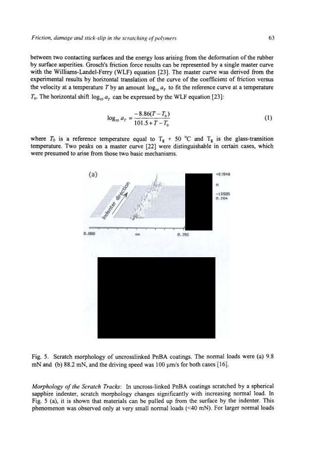
Friction forces generated by polymer surfaces generally do not obey the classical Amonton's and Coulomb's laws [21], in which the frictional force is proportional to the normal load and independent of the sliding speed. Because of the viscoelastic nature of polymers, the friction force depends on the sliding speed and temperature. The experiments done by Grosch [22] suggested that two mechanisms contribute to the friction of rubber materials: the adhesion
64 |
Scratching of materials and applications |
(>60 mN), the scratch track displays long and deep pits accompanied by relatively short and shallow gashes, as shown in Fig. 5 (b). The horizontal force decreases during slip when the indenter moves quickly, whereas it increases when the indenter is temporarily blocked in the stick stage by the undamaged part of the coating material. As a result, the center of a scratch track oscillates considerably up and down.
Scratching Behavior ofCrosslinked PnBA Coating
Horizontal Force during Scratching: Unlike uncross-linked PnBA coating, the surface of crosslinked PnBA coating is not sticky. Figure 6 shows the horizontal force during scratching of crosslinked PnBA coating (two thicknesses 57 and 235 Jlm). Here, the horizontal force starts from zero at no normal load in contrast to the uncrosslinked PnBA coating, for which the horizontal force has a residual value (- 6 mN) as the normal load approaches zero. This indicates that crosslinking has dramatically decreased the surface tackiness of PnBA coating; therefore, the interfacial energy between the coating and the indenter is almost zero. For the 235-Jlm coating, the horizontal force can be fitted by the Sneddon equation [24] for normal loads of less than 100 mN (see Fig. 6) if the horizontal force is assumed to be proportional to the contact area. The constant of proportionality between the horizontal force and the contact area was found to be 10.85 MPa, which is about 2.5 times the shear modulus. The Sneddon equation, which is applicable to larger contact areas than the Hertz equation, shows the relation between the normal load P and the contact radius a
|
|
(2) |
or the displacement 8 : |
|
|
O=::lnR+a |
(3) |
|
2 |
R-a |
|
where R is the indenter radius and E and |
v are |
Young's modulus and Poisson's ratio, |
respectively, for the half space. The penetration D of the indenter into the coating at a normal load of 100 mN is estimated to be about 61 Jlm, which is about 26% of the thickness of the coating. Young's modulus E of 12.7 MPa (determined by nanoindentation measurement) and Poisson's ratio of v = 0.5 were used in the calculation. A finite element analysis [18] was performed for the elastic contact between a rigid spherical indenter (76 Jlm in radius) and a soft thin film coated on a rigid substrate. The contact radius and displacement were calculated for two thicknesses (100 and 250 Jlm) of the thin film. The results of the analysis indicated that the film thickness has little effect on contact radius despite a significant effect on displacement.
The discrepancy of the contact radius between the thin film and a half-space medium is less than 5% for a contact radius of up to 0.8R. The change in contact radius with film thickness from 250 to I00 Jlm is less than 2%. Therefore, the Sneddon equation derived for a half space can be used for the 235-Jlm coating.

Friction, damage and stick-slip in the scratching of po/nners |
|
65 |
||||||||||||
|
500 |
f |
• |
|
|
|
|
|
|
|
|
·~ |
||
|
5111m |
|
|
|
|
|
|
|
||||||
|
f, |
• |
• 1 • • |
• |
|
l' |
|
|
|
|
|
|||
|
400 |
|
o |
2~511m |
|
|
|
|
|
|
|
|
||
z |
|
-- - |
-·- |
|
|
|
|
|
|
|
|
|
||
|
|
|
|
|
|
|
|
' |
' |
|
|
|
|
|
.§. |
|
|
|
|
|
|
|
|
|
|
|
|
|
|
]j |
300 |
|
|
|
|
|
|
_yV· |
|
|
|
|
|
|
., |
|
|
|
|
|
|
|
|
|
|
|
--!Jf |
||
!:! |
|
|
|
|
|
|
|
|
|
|
|
|
||
If |
|
|
|
|
|
|
|
|
|
-- |
|
|
||
2 |
|
|
|
|
|
|
|
' : |
|
>r- |
||||
c |
200 |
|
|
|
|
|
|
-: |
|
|
|
|
I |
|
|
|
|
|
|
|
·-- ...• ---- |
|
|
|
|
||||
-~ |
100 |
|
|
'~- |
|
|
|
|
|
|||||
J: |
|
|
' |
|
#00 .... · -- |
|
|
|
|
|||||
|
|
|
|
-·- |
|
|
|
|
|
|
|
|
||
|
|
|
|
|
|
Drivirig Speed =20 llfil/sec |
|
|||||||
|
|
|
|
|
|
|
|
200 |
300 |
|
400 |
500 |
||
|
|
|
|
|
|
|
Nonnal Load (mN) |
|
|
|
|
|||
Fig. 6. Horizontal force during the scratching of crosslinked PnBA coating. The solid line is the curve fitting for the 235-!lm-thick coating with the Sneddon equation [16].
Mechanisms for Scratch Damages: Because cross-linked PnBA coating behaves as an elastomer, below a critical normal load, which depends on the thickness of the coating, the crosslinked coating recovers elastically after being scratched and leaves no discernible damage. Above the critical load, the coating is damaged and, depending on the coating thickness, shows two distinct damage mechanisms. Eight different thicknesses ranging from 15 to 235 1-1m were examined.
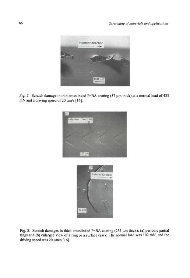
For thin coatings (<70 1-1m), the scratch damage is believed to be a combination of delamination and spallation (called type I damage hereafter). Figure 7 clearly shows that the coating is delaminated under the shear stress ahead of the indenter and removed by spallation. This coating stripping process was explained by Benjamin and Weaver [25] and Weaver [26] as follows: The shearing effect between the coating and the substrate is greatest at the tip of the indentation, and this is where the rupture of adhesive bonds would first occur at the critical load. Because of the horizontal motion of the indenter, the rupture of adhesive bonds between the coating and the substrate would extend, and the sheared material would be pushed away by the indenter. Figure 6 (see the solid circles) shows that the critical load (433 mN) coincides with an abrupt variation in horizontal force. There is an increase in horizontal force when the coating is damaged. Type I scratch damages offer opportunities for the study of adhesion between a coating and its substrate [25, 27-29]. For soft thin coating/soft substrate systems, the indenter sinks much deeper into the surface and a failure mechanism such as buckling due to compressive strain ahead of the indenter may instead occur [30].
In thick coatings (>120 1-1m), the scratch damage appears as periodic partial rings that are concave with respect to the scratching direction as shown in Fig. 8 (a) (called type II damage hereafter). In contrast to thin coatings (<70 1-1m) in which the horizontal force increases when the coating is damaged, there is a decrease in horizontal force (see the open squares in Fig. 6).