

книги / FISMA and the risk management framework the new practice of federal cyber security
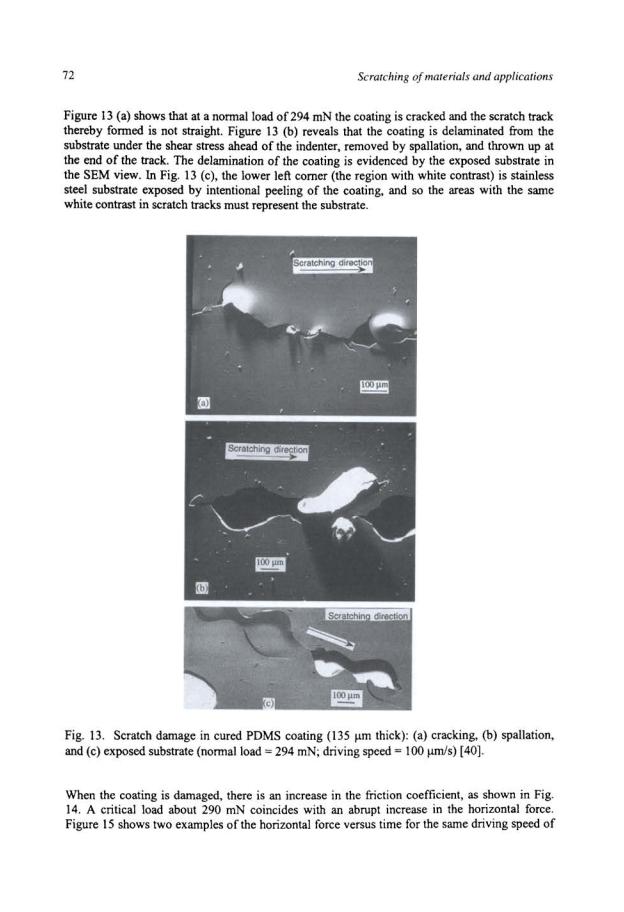
..pdfFriction, damage and stick-slip in the scratching of polvmers |
67 |
when such damage begins to occur in thick coatings. The drop in horizontal force may be caused by a sudden increase in the local compliance of the sample in front of the indenter when such cracking occurs, which, in tum, results in an abrupt drop of the load cell output. Similar cracking patterns were found in other organic and inorganic materials [31-35]. Scanning electron micrographs reveal that those partial rings are surface cracks [Fig. 8 (b)]. The driving force for this type damage is mainly the horizontal force. The tensile stress produced in the coating behind a moving indenter due to the presence of a friction force is well known [36]. The application of a horizontal force to the normally loaded surface adds a compressive stress in front of the sliding sphere and a tensile stress at the rear. The result of this is to decrease the critical normal load for tensile cracking and produce in the sliding track a series of parallel curved cracks [37]. It appears that the mechanism of the type II damage corresponds to tensile cracking. If so, the primary material property governing the damage is the fracture toughness.
The critical normal load increases with the coating thickness regardless of the damage mechanisms, as shown in Fig. 9. Similar thickness dependence of the critical normal load was observed by Gupta and Bhushan [38] in amorphous carbon coatings in which the failure mechanisms were delamination and spallation in thin coatings (:o; 30 nm) and tensile cracking in thick coatings (:2: 100 nm).
|
······-··············:······ |
|
|
||
|
|
! Speed =~Jllll/8eC |
|
||
|
|
··..-t········· |
|
|
|
|
|
......;. .... |
········-············ |
||
|
···················..:..............;......... |
o. |
|||
::~ |
|
||||
----- ~~.. |
-- --~--- |
~ |
j |
|
|
so |
100 |
150 |
200 |
250 |
|
|
Film Thickness (jim) |
|
|
||
Fig. 9. Thickness dependence of the critical normal load for the crosslinked PnBA coatings:
(•) thin coatings and (o) thick coatings. The driving speed was 20 llmls [16].
For type I damage in thin coatings, the explanation could be that the stresses around the indenter fall off with the depth [36]; the application of correspondingly greater loads would then be required to produce the critical interfacial shear stress for the coating to be delaminated from the substrate. For thick coatings, the results could be explained by the realization that the horizontal force for tensile fracture in the coating should be proportional to the thickness of the coating. More experiments are needed to understand the transition between the two mechanisms in Fig. 9 as a function of thickness, namely, whether the transition is sharp or more general so as to have a mixed region.
68 |
Scratching of materials and applications |
SCRATCHING BEHAVIOR OF ELASTOMERIC POLY(DIMETHYLSILOXANE) COATINGS
Poly(dimethylsiloxane) (PDMS) is widely used in many industrial applications such as coatings, seals, gaskets and adhesives [39]. PDMS, which is a very mobile polymer with a glass-transition temperature (Tg) of -125 °C, maintains its thermal stability and mechanical, chemical, and electric properties between -70 and 250 °C. These same features make PDMS attractive for fundamental studies of scratch deformation. In this section, we present experimental results for friction and damage characteristics during scratch tests ofPDMS coatings on stainless steel.
The cured PDMS was coated on a 90-)lm-thick substrate of stainless steel shim. The samples were cut in the shape of a rectangle (l5xl0 mm2). Scratch tests were performed with a spherical sapphire (76-!lm-radius) indenter unless specified otherwise.
The morphology of the scratches was examined with scanning electron microscopy (SEM). Samples for SEM were made by coating the specimen surface with a very thin gold layer (ca. 10 nm thick) by thermal evaporation. For the purpose of detecting the steel substrate exposed because of scratching damage, an original (as-scratched) sample without a gold layer was also examined. The PDMS coating at a comer of the sample was intentionally peeled off for exposure of the substrate. Surprisingly, this sample worked as well and produced quality photos with sharp contrast.
To confirm the inherent viscoelastic loss property of the PDMS material, we conducted dynamical mechanical test for bulk cured PDMS with a Rheometric Solid Analyzer (RSAII) in a compression mode. In the dynamical test, oscillating strains were applied to the sample for measurement of the storage modulus (£')and loss modulus (£"), as well as the loss tangent (£"/£').E' quantified the elastic response of the sample. E"!E indicated the level of viscous energy loss experienced in the test. The sample (2.4 mm thick) was cut in the shape of a circular plate with a radius of 8.5 mm. The compressive storage modulus and loss tangent were determined simultaneously at frequencies ranging from 0.159 to 15.9 Hz. A static precompression (corresponding to a strain ofO.S%) was applied so that the sample was always in compression. An oscillating strain with amplitude of 0.45% was imposed for implementation of the measurement.
Effect ofNormal Load on the Horizontal Force during Scratching
Below a critical normal load (see the Scratch Damage and Mechanism section), the PDMS coating recovers after being scratched. Above the critical normal load, the coating is damaged. This section describes the features of horizontal force during scratching in which the PDMS coating recovers and leaves no visible damage behind.
Figure l 0 |
shows the effect of the normal load on the average |
horizontal force |
(error |
bar |
represents |
the standard deviation) during the scratching of cured |
PDMS coatings |
(135 |
)lm |
thick). The horizontal force starts from zero at zero normal load in contrast to uncrosslinked PnBA coatings in which the horizontal force has a residual value (-6 mN) as the normal load approaches zero. Moreover, the friction coefficient decreases with increasing normal load.
The results in Fig. 10 can be understood as follows: during scratching, the contact area between the indenter and the coating is determined by the elastic contact, and the frictional force is proportional to the contact area. For a spherical indenter of radius R, the contact area between
Friction, damage and stick-slip in the scratching ofpolymers |
69 |
the indenter and the material being scratched is given as a function of the normal load P by the Hertz theory [5, 6]. If the frictional force is assumed to be proportional to the contact area, the horizontal force f and friction coefficient p would depend on P according to the following relations:
f |
=CP2r3 |
(4) |
f.1 |
= f; P =cr"3 |
(5) |
where C = 1tS[RIK)213 = JZS[3(I-v2)R/4E]213, in which Sis the interfacial shear strength (force per unit area) between the indenter and the material; v and E are Poisson's ratio and Young's modulus of the material, respectively; and K is defined as shown.
In Fig. IO, the curve fittings with Eqns. (4) and (5) are also shown. The fitting parameter SIK213 found is 31.28 (Pa)113 for Fig. IO (a) and 31.33 (Pa)113 for Fig. IO (b). This agreement and the
good fittings imply that, within the range of normal loads employed in Fig. I0, the contact between the indenter and the PDMS coating obeys the Hertz theory, and the friction force is proportional to the contact area. The constant of proportionality between the horizontal force and the contact area is 0.78 MPa for both Fig. IO ((a) and (b)). This proportionality constant can be compared with the shear modulus, which is 0.73 MPa. This comparison implies that the
0.3 |
~- ·• |
f f |
f f f .•i 10 |
|
|
Driving Speed = 20 ~m/s |
j |
0.2L_~~--L-~~~~~-'--'----"-'' 0
0 |
50 |
100 |
150 |
200 |
Normal Load (mN)
Normal Load (mN)
Fig. I0. Horizontal force and friction coefficient as functions of the normal load during the scratching of cured PDMS coating (135 Jlm thick): (a) 76-Jlm-radius indenter and (b) 38I-Jlm- radius indenter. Dotted lines are curve fittings with the Hertz theory [40].
70 |
Scratching of materials and applications |
interfacial fracture strain is about 1.07 if Hooke's law holds for this elastomer. For the same fracture strain in tension, it means an elongation of2.9 times.
For simplicity, we have adopted the Hertz theory in the calculation of the contact area. Since the Hertz theory is for the contact of two spheres or a sphere with a half-space, it is not exactly the situation here. However, according to the finite element analysis [18] mentioned in previous section, the coating thickness has little effect on contact radius despite a significant effect on displacement.
Effect ofDriving Speed
Figure 11 represents the friction coefficient as a function of the driving speed (nominal scratching speed). The friction coefficient falls to small values at low speeds. With increasing driving speed, the friction coefficient increases. The results suggest that the scratching of the PDMS coating is a rate process. The viscoelastic property of the coating influences its frictional behavior.
|
0.9 |
|
|
|
|
|
0.8 |
|
|
|
|
c 0.7 |
|
|
|
|
|
" |
|
|
|
|
|
·c:; |
|
|
|
|
|
|
|
|
|
|
|
lE |
|
|
|
|
|
<D |
|
|
|
|
|
0 |
0.6 |
|
|
|
|
0 |
|
|
|
|
|
|
|
|
|
|
|
c: |
|
|
|
|
|
0 |
|
|
|
|
|
i3 |
|
|
|
|
|
·c: |
0.5 |
|
|
|
|
u. |
|
|
|
|
|
|
|
|
|
|
|
|
|
,." |
|
Normal Load ; 98 mN |
|
|
0.4 |
|
|
|
|
|
0.3 |
L~----- - |
~---~• -~~- •• |
--•-·-~~---- |
|
|
|
10 |
100 |
1000 |
10' |
Driving Speed (~m/sec)
Fig. 11. Driving speed effect on the friction coefficient during the scratching of cured PDMS coating (135 J.Lm thick) [40].
Schallamach [41) suggested that the frictional sliding of rubber is a thermally activated rate process; the main reason for this assumption is the observed temperature dependence of frictional sliding. No detailed molecular model was given, but the general picture was that rubber molecules move due to thermal agitation at the sliding interface. The rate of jumps that the molecules make depends on temperature. In the absence of external stress, their jump direction is completely random. An applied frictional stress directs the jump in the direction of stress.
Figure 12 shows that both storage modulus and loss tangent increase with frequency in a dynamic mechanical measurement. We consider that the driving speed dependence of the friction force directly corresponds to the frequency dependence of the material mechanical property [42]. The frequencyf can be estimated as follows:
f=VI2a |
(6) |

Friction, damage and stick-slip in the scratching of polnners |
|
|
71 |
|||
1.05 |
|
|
|
~0.07 |
|
|
|
|
|
|
; |
|
|
|
|
0 |
l 0.06 |
|
||
|
|
|
• |
|
||
|
|
|
~< |
0.05 |
~ |
|
|
|
|
|
4 |
|
-1 |
|
|
|
|
j |
|
] |
|
|
|
|
-j |
0.04 |
~ |
|
|
|
|
j~ |
0.03 |
|
|
|
|
|
i |
|
|
0.1 |
10 |
|
|
|
||
|
|
|
Frequency (Hz) |
|
|
|
Fig. I2. Frequency dependence of the storage modulus and loss tangent of cured PDMS material [40].
where a and V are the contact radius and the moving speed of the indenter, respectively. According to Hertz's theory, a can be expressed as follows:
(7)
where Pis the applied normal load, R is the indenter radius, v and E are Poisson's ratio and Young's modulus, respectively, of the PDMS material. Therefore, the relationship between/ and V can be expressed as follows [42]:
(8)
The scratch speeds of IO, IOO and 1000 J.lrnls in Fig. II correspond to 0.03, 0.3 and 3 Hz, respectively. Figure I2 shows that between frequencies of 0.3 and 3 Hz, the loss tangent increases by 4I %. This can be compared with Fig. I I, in which between speeds of I00 and 1000 J.lm/s, the friction coefficient increases by 39%. Therefore, it is likely that the friction, in addition to its proportionality with the contact area, has its origin in the anelasticity of the material.
Scratch Damage and Mechanism
As mentioned earlier, below a critical normal load, the PDMS elastomer coating recovers after being scratched and leaves no visible damage. Above the critical normal load, the coating is damaged by a combination of through-thickness cracking and delamination at the coating/substrate interface.

Friction, damage and stick-slip in the scratching ofpolvmers |
73 |
100 J.Ull/s. For a normal load of 278 mN, which is below the critical load, the film is intact, and the horizontal force varies only slightly(± 5%). However, for a normal load of294 mN (above the critical load), the coating is damaged, and the horizontal force displays significant fluctuations (±10%). When cracking and spallation occur, the horizontal force drops because the indenter dives abruptly down and moves quickly along the substrate surface. Then the indenter is temporarily blocked by the undamaged coating material ahead, so the horizontal force increases and builds up to a maximum to cause damage again, and the cycle repeats.
Critical Normal Loadfor Scratch Damage
Obviously, it is important to measure the coating/substrate interfacial strength and to characterize the factors influencing it. The critical normal loads measured in scratch tests have been used in assessing the adhesion in the coating/substrate systems. The critical normal load is defined as the load at which a well-defined failure event occurs. If this failure event represents coating detachment, the critical normal load can be used as a semiquantitative measure of coating/substrate adhesion [25, 27, 28]. The critical load can also be determined from the observation of a sudden change in the slope of the curve of the horizontal force versus the normal load. There are discussions of various factors that can influence the critical normal load of delamination. For example, critical normal loads may be affected by coating thickness (as seen in previous section on crosslinked PnBA coatings) and scratching speed. These are discussed below.
|
150 |
|
|
|
|
|
|
|
|
|
|
|
|
|
|
|
|
|
|
|
|
|
|
|
|
Jf |
|
|
|
z |
120 |
|
|
|
|
|
|
|
|
|
|
|
|
|
|
|
|
|
|
|
|
|
-- t'--·-- .. |
|
!.' |
|
|
||
.§. |
90 |
|
|
|
|
|
|
|
,{ |
' |
l |
|||
{1. |
|
|
|
|
|
|
|
|||||||
~ |
|
|
|
|
|
|
|
|
|
|
|
|||
~ |
60 |
|
|
|
|
.. |
..- -·- |
|
|
|
|
|
|
|
·§ |
|
|
|
|
|
|
|
|
|
|
|
|||
:I: |
|
|
|
|
|
|
|
|
|
|
|
|
|
|
|
30 |
|
|
' |
• |
|
|
Driving Speed " 100 J1ml5eC |
|
|
||||
|
|
|
|
|
|
|
|
|||||||
|
|
|
' |
' |
|
|
|
|
|
|
|
|
|
|
|
0 |
|
' |
|
100 |
150 |
200 |
|
|
|
|
|
||
|
|
|
|
|
|
|
|
|||||||
|
|
|
|
|
|
|
|
|||||||
|
0 |
|
|
50 |
250 |
|
300 |
350 |
||||||
Normal load (mN)
Fig. 14. Horizontal force before and after coating is damaged during the scratching of cured PDMS coating(l35Jlm thick) [40].
The critical normal load increases with the coating thickness, as shown in Fig. 16. It is known that the stress around the indenter falls off quickly with depth [36]. Therefore, for delamination of the coating from the substrate, larger forces are required for thicker coatings to produce the same critical interfacial shear stress as for thinner coatings. However, there is no relation available between the interfacial energy and the critical load.

74 |
|
|
|
|
|
Scratching of materials and applications |
||
|
160 1-e---Nonnalload = 278.3 mN |
~~ |
||||||
|
140 |
|
|
_.__ Normal load = 294 mN |
|
|
|
|
|
|
|
|
|
|
|
|
|
z |
|
|
|
|
|
|
|
|
,S |
120 |
|
|
|
|
|
|
|
<l) |
|
|
|
|
|
|
|
|
2 |
|
|
|
|
|
|
|
|
0 |
|
|
|
|
|
|
|
|
u_ |
|
|
|
|
|
|
|
|
g |
|
|
|
|
|
|
|
|
c |
100 |
|
|
|
|
|
|
|
N |
|
|
|
|
|
|
|
|
0 |
|
|
|
|
|
|
|
|
"§ |
|
|
|
|
|
|
|
|
I |
|
|
|
|
|
|
|
|
|
80 |
|
|
|
|
|
|
|
|
|
|
|
Driving Speed = 100 ~m/sec |
||||
|
60 |
|
|
|
|
|
|
|
|
|
|
|
|
|
|
|
|
|
0 |
20 |
40 |
60 |
80 |
100 |
|
|
Time (sec)
Fig. 15. Horizontal force versus time during the scratching of cured PDMS coating (135 Jlm thick; normal load= 278.3 and 294 mN; driving speed= 100 J.Lrnls) [40].
It is also interesting to know how the scratching speed affects the occurrence of scratch damage in PDMS coatings. Figure 17 compares two curves of the horizontal force versus time obtained at the same normal load of 294 mN but at different driving speeds. The PDMS coating was damaged at a scratching speed of 100 Jlmls, but it remained intact at a speed of 250 J.Lrnls. For the latter speed, a normal load of 319 mN was required to damage the coating. As also shown in Fig. 15, the horizontal force displays much more fluctuation when the coating is damaged.
Coating Thickness ( ~m)
Fig. 16. Thickness dependence of the critical normal load for cured PDMS coating [40].

Friction, damage and stick-slip in the scratching of polvmers |
75 |
z
.s
~"
0 lL
«i
c:
0
N
"§
I
150
_..._ Speed = 100 ~m/sec
140
o Speed = 250 ~m/sec
130
120
110
100
90
Normal Load =294 mN
80
0 |
20 |
40 |
60 |
80 |
100 |
Time (sec)
Fig. 17. Horizontal force versus time curves during the scratching of cured PDMS coating (135 flm thick; normal load= 294 mN; driving speeds= 100 flmiS and 250 f.lm/S (40].
Figure 18 shows that the critical normal load increases with the driving speed. Since it is possible that time is needed to nucleate damage, the coatings are more easily damaged at a lower scratching speed than at a higher speed. Steinmann et al. [29] found that the critical load of a chemical-vapor-deposited TiC coating on steel decreased with increasing scratching speed. The positive scratching speed dependence of critical load for PDMS coating may be unique for viscoelastic materials. Ni and Le Faou [35] found that the critical horizontal force for poly(ethylene terephthalate) (PET) film increases with increasing scratching speed; the mechanism of scratch damage is taken as surface shear yielding.
400
z 350 |
|
|
|
|
|
t |
|
|
|
|
|
|
yf t |
||
.s |
|
|
|
|
f |
t y |
' |
'0 |
|
|
|
|
y |
|
|
ro |
|
|
|
|
|
||
0 |
|
|
Damage |
|
' |
|
|
..J |
300 |
|
|
|
|
|
|
lii |
|
|
|
|
|
|
|
E |
|
|
|
t |
|
|
|
0 |
|
|
|
|
|
|
|
z |
|
|
" |
' |
No Damage |
j |
|
lii |
|
|
|
|
|||
(.) |
|
|
|
|
|
||
:;::; |
|
|
|
|
|
|
|
·c: |
250 [ |
|
' |
|
|
|
|
() |
|
|
|
|
|
||
|
|
|
|
|
|
||
|
200 |
" |
I I I 11! |
I I |
111! |
|
|
|
10 |
|
|
100 |
|
1000 |
|
Driving Speed (IJm/sec)
Fig. 18. Driving speed dependence of the critical normal load for cured PDMS coating (135 f.lm thick) [40].

76 Scratching of materials and applications
Figure 18 serves as a map, with the line separating regions of damage and no damage. A rule for good coating development is to push the line upward and to the left.
SLIP PROCESS OF STICK-SLIP MOTION IN THE SCRATCHING OF STYRENEACRYLONITRILE COPOLYMER
Styrene-acrylonitrile (SAN) copolymer supplied by Dow Chemical Company was chosen as the testing material because it undergoes only plastic deformation (no cracking) when being scratched, and its plastic properties have been studied [43, 44]. The samples were cut in the shape of a rectangular parallelepiped of 15xl0x5 mm3. The surfaces of the sample were mechanically polished, first with 1 J..lm and then 0.05 J..lm alumina slurries. A diamond indenter (136° conical) was used in scratch test. The scratches were made at low speeds ( :::20 J..lrnls), so that heating is negligible. The morphology of the scratches was examined in an atomic force microscope.
General Features ofthe Slip Process
A spring-block model [45] is often used to represent schematically the sliding bodies where a slider block is pulled with a spring against a counterface at a constant velocity. Such a model can well explain the occurrence of stick-slip phenomenon. During the stick stage of stick-slip motion, the block is fixed and the spring elongation expresses the storage of elastic energy. When the shear stress between the block and the counterface reaches contact strength, a sudden slip occurs. During this slip stage, the spring is shortened, which releases a part of the previously stored elastic energy.
L
k
Fig. 19. A simple model of the scratch system [46].
Figure 19 shows a simple spring-block model of the scratch system. The effective spring constant k of the mechanism connecting the step motor (moving at a constant speed Vo) to the slider can be obtained from the slope of the horizontal force versus time curve (Fig. 20) during the stick stage. The total mass of the slider and sample is m. L is the normal load applied to the specimen and x is the real scratch distance moved by the indenter. The force balance in the sliding direction is
k(V0 t - x) - f = mX |
(9) |