книги / FISMA and the risk management framework the new practice of federal cyber security
..pdfAn overview of the potential of quantitative coating adhesion measurement bv scratch testing |
I37 |
INTRODUCTION
The scratch test has been used for many years to provide a measure of coating/substrate adhesion [1-6]. In the normal configuration of the test a diamond stylus is drawn across the coated surface under an increasing load until some well-defined failure occurs at a load which is often termed the critical load, Lc. Many different failures are observed which include coating detachment, through-thickness cracking and plastic deformation or cracking in the coating or substrate [7-10]. In fact it is usual that several different failure modes occur at the same time and this can make results of the test difficult to interpret.
The failure modes observed in the scratch test depend on many factors and are most easily characterised in terms of the hardness of both substrate and coating (Figure 1). In the case of a typical Rockwell 'C' diamond indenter (120° cone with 200j.lm hemispherical tip), for soft coatings and soft substrates the test is dominated by plastic deformation and groove formation and little or no cracking is observed except at very high loads. For hard coatings on soft substrates deformation of the substrate is predominantly plastic whilst the coating may plastically deform or fracture as it is bent into the track created by plastic deformation of the substrate. Soft coatings on a harder substrate tend to deform by plastic deformation and some extrusion of the coating from between the stylus and the substrate may occur. Considerable thinning of the coating by plastic deformation will occur before plastic deformation and fracture of the substrate becomes significant. For hard coatings on hard substrates plastic deformation is minimal and fracture dominates the scratch response.
Bulk
Fracture
Interfacial
Failure
Plastic
Deformation
Through-thickness
Fracture
Coating hardness, H
c
Fig. I. Schematic showing the various scratch test failure modes which dominate as a function of coating and substrate hardness (He and H5, respectively).
As the indenter becomes sharper, plastic deformation becomes more localised to the surface and it is easier to prevent plastic deformation of the substrate. In such cases the results of the test are
138 |
Scratching of materials and applications |
easier to analyse and quantify, particularly for more modem depth sensing indentation and scratch systems. However, damage to the diamond stylus during the test becomes much more significant as its sharpness increases. The choice of stylus thus represents a compromise between damage and ease of data analysis - for industrial hard coatings of reasonable thickness (>1Jlm) the Rockwell 'C' stylus has proved very successful whilst for sub micron coatings a conical indenter with a tip radius of a few microns is more suitable.
The scratch test is not well-suited to measure the adhesion of soft coatings but can give some information if the interfacial shear strength is less than the shear strength of either the coating or substrate. In general, the scratch test is most effective if the substrate does not plastically deform to any great extent. In such cases the coating is effectively scraped from it and the uncovering of the substrate itself can be used as a guide to adhesion. However, it is difficult for this to be quantified. Detection of the uncovered substrate may be a problem unless post facto chemical analysis methods can be employed. However, some success is possible by measuring the change in friction during the scratch if the coating and substrate behave differently. For instance, an increase in friction may be observed if a high friction coefficient substrate in uncovered during the test.
The scratch adhesion test is much more useful for hard coatings, particularly when these are deposited on softer substrates. For a harder coating on a soft substrate the spallation and buckling failure modes arise from interfacial detachment [8,9,10) and can thus be used as the basis for an adhesion test. Both may be quantified in some circumstances and are discussed in this paper. The origin of these failure modes and the theoretical basis for analysing them is introduced in the next section, together with finite element results aimed at improving quantification.
OVERVIEW OF SCRATCH ADHESION TESTING
Requirements for quantification ofthe scratch test
If the scratch test is to be fully quantitative it must deliver a parameter which is representative of the state of adhesion of the interface but is not related to the other properties of the coating/substrate system such as hardness. The best parameter for this is work of adhesion which is a measure of the chemical bonding across the interface. However, most adhesion tests do not measure this basic adhesion but produce a practical adhesion measurement conflating basic adhesion with other factors which can be specific to a given material pair or test method [11-13]. Film adhesion is often characterised by the strain energy released per unit increase in delamination area, G, which is sometimes referred to as the interfacial fracture energy and can be used to generate an interfacial fracture toughness, Ki. For most practical purposes this measurement of practical adhesion is sufficient but it should be corrected for method-specific factors to ensure that the test is widely applicable and the data produced can be compared with that from other test methods.
The scratch test is usually only regarded as semi-quantitative as there are a number of intrinsic and extrinsic parameters which are known to affect the measured critical load (Table 1). Many of these intrinsic factors are instrument-specific and require a careful calibration approach if results are to be compared between instruments. However, the extrinsic factors such as coating thickness and substrate hardness must also be known if the results of the test are to be understood. These parameters, together with the residual stress in the coating and its Young's
140 |
Scratching of materials and applications |
There are thus four requirements for a quantitative scratch adhesion test:- !) An adhesion-related failure mode,
2)A well-defined failure mechanism,
3)A method to identify that adhesion failure has occurred, where it is located and the size of the failure,
4)A method of determining the stresses which cause failure.
These will be discussed in more detail in the following sections.
Scratch test failure modes
Soft coatings: In general soft coatings (hardness<5GPa) fail by plastic deformation whether deposited on softer or harder substrates. Coatings deposited with a porous microstructure (e.g. the open columnar structures produced by vapour deposition at low temperatures) may also show some evidence of fracture but this is not widespread. The scratch test is not very useful for assessing adhesion unless the interfacial shear stress is less than the shear strength of the softer component. In such cases stripping or flaking of the coating may occur if the adhesion is very poor but often there is little to see but a plastic groove after the test is complete.
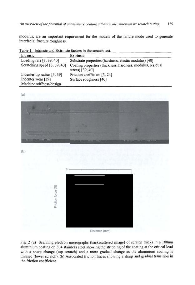
When a soft coating is deposited on a very different, harder substrate, such as aluminium or gold on glass, the detection of interfacial failure is much easier. As the load is increased in the scratch test the soft coating is progressively plastically deformed until at the critical load the substrate is uncovered. This can be detected by a colour change or by the use of surface analysis techniques such as x-ray photoelectron spectroscopy (XPS) which are surface sensitive. However, XPS analysis is not always practical since failure does not occur exactly at the interface - in such cases x-ray mapping or backscattered imaging in the SEM can be used to determine a critical load but this does not represent the load for interfacial detachment (Figure 2a), rather this is the load at which the coating has been scraped off the substrate. Unless there is a sharp transition when the coating is stripped, indicating some adhesive failure, selecting a critical load for coating detachment is almost impossible in such cases but the scratch test critical load may give an indication of the resistance to scratch damage of the coated surface.
An alternative method to detect the appearance of the substrate is to analyse the friction traces developed during the scratch test. In the case of aluminium coatings on 304 stainless steel the friction coefficient increases when the substrate is uncovered (Figure 2b). The sharpness of the friction transition in the plot of friction coefficient versus load mimics the sharpness of the transition observed in backscattered electron images in the scanning electron microscope. However, such clear results are not often observed.
The earliest attempts at scratch test quantification by Benjamin and Weaver [7] are most applicable when thin coatings are plastically deformed in the scratch test. According to these authors the critical shearing force for coating removal, t, is a function of the scratch geometry, the substrate properties and the frictional force on the stylus. Thus, for a stylus of radius, R,
(1)
An overview of the potential of quantitative coating adhesion measurement by scratch testing |
I41 |
where the radius of the contact A=(LchtH)112, Lc is the critical load, H is the hardness of the substrate material and k is a constant varying between 0.2 and 1.0. The critical shear stress increases as the substrate hardness increases which agrees with experiment. This model assumes full plastic deformation (which is only applicable in a limited range of cases) and does not show the influence of coating thickness.
For soft polymeric coatings on harder metallic substrates the shear stress applied to the coating during the scratch test can lead to regions of delamination extending ahead of the stylus. In such cases a fracture mechanics model has been developed to assess adhesion based on the assumption that the stress field around a moving indenter can be given by the Boussinesq solution [14, 15]. This is clearly not a complete solution as it does not deal with elastic mismatch at the coating substrate interface but generates strain energy release rates comparable to those obtained by different adhesion test methods. However, the method requires knowledge of the area and geometry of delamination which is not always easy to determine if the coating is not transparent and the same mechanism of failure is not often observed for other coating systems. For this reason the model is not widely applicable.
In general only semi-quantitative measurements of adhesion of soft coatings can be achieved by scratch testing and alternative adhesion test methods are preferred (e.g. tensile and peel tests [16], blister tests [17], superlayer tests [18]). Since soft coatings are usually quite ductile and may be mechanically manipulated without failure such mechanical tests are relatively easy to perform. The main problem is that the work done is not solely governed by the energy expended in detachment and deconvoluting the measurements in a way which separates the work of adhesion from other energy absorbing mechanisms is difficult [19].
Hard coatings: In the context of this chapter hard coating refers to coating materials with a hardness of greater than 5GPa. The failure modes can be broadly split into four categories:
1.Through-thickness cracking - including tensile cracking behind the indenter [8,20], conformal cracking as the coating is bent into the scratch track [8,20] and Hertzian cracking
[8].These cracks may extend into the substrate if it is sufficiently brittle but are usually stopped at the interface in a hard coating on a softer substrate.
2.Coating detachment - including compressive spallation ahead of the indenter [8,20], buckling spallation ahead of the indenter [8] or elastic recovery-induced spallation behind the indenter [8, 21].
3.Chipping within the coatingusually observed for thick coatings on a softer substrate. The
scratch test cannot practically measure the adhesion of coatings greater than 50J.!m thick in its conventional form since it is impossible to generate sufficiently large stresses at the interface before chipping of the coating occurs.
4.Chipping within the substrate - for brittle coatings on brittle substrates where the adhesion is good the system tends to behave in the same way as a brittle bulk material and unless the coating is sufficiently thick chipping of the substrate will occur.
The type of failure which is observed for a given coating/substrate system depends on the test load, the indenter radius, the coating thickness, the residual stress in the coating and the
142 |
Scratching of materials and applications |
substrate hardness and interfacial adhesion. Generally the critical load at which a failure mode first occurs, or occurs regularly along the track, is used to assess the coating though there is a distribution of flaws and hence of failures in most cases [6]. Comparisons between different coatings are only valid if the mechanism of failure is the same which requires careful post facto microscopical examination for confirmation.
The adhesion related failures which are the basis of the scratch adhesion test for hard coatings are buckling and spallation [9,10] and are described in more detail in the next section.
Failure mechanisms related to adhesion for hard coatings
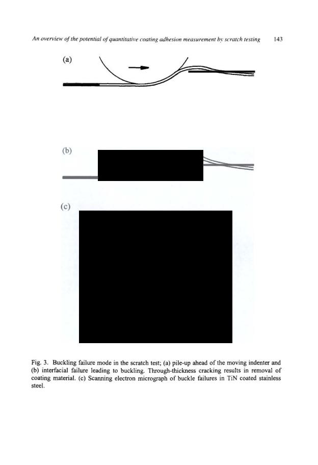
Buckling: This failure mode is most common for thin coatings (thickness typically <l01-1m) which are able to bend in response to applied stresses. Coatings much thicker than this limit will tend to show through-thickness fracture at stresses lower than those necessary to cause buckling and will fail by wedge spallation (see next section). Failure occurs in response to the compressive stresses generated ahead of the moving indenter (Figures 3a and 3b). Localised regions containing interfacial defects allow the coating to buckle in response to the stresses and individual buckles will then spread laterally by the propagation of an interfacial crack. Spallation occurs when through-thickness cracks form in regions of high tensile stress within the coating. Once the buckle has occurred, the scratch stylus passes over the failed region crushing the coating into the surface of the scratch track formed in the substrate. Coating removal can be enhanced at this point or the failure may disappear completely depending on its size and the toughness of the coating.
Buckling failures typically appear as curved cracks or patches of damage extending to the edge of the scratch track or beyond. They are often delineated by considerable coating fragmentation and have major crack planes perpendicular to the coating/substrate interface. In most cases buckles form in the region of plastic pile-up ahead of the moving indenter (Figure 3c). The size of the buckle is typically less than or equal to the extent of pile-up. This would imply that the pile-up process controls the buckle failure mode to a great degree. This explains, to a large extent, the increase in critical load with substrate hardness for titanium nitride tool coatings on steel which is often reported [I] since in such coatings the buckle failure mode dominates. As the steel hardness increases plastic pile-up ahead of the indenter is reduced and the bending stresses induced in the coating by the pile-up are limited. A higher normal load is needed to develop equivalent pile-up and bending stresses and thus the critical load increases. The correlation between buckle diameter and pile-up diameter is very close for alumina scales on the oxide-dispersion strengthened alloy MA956 or TiN coating on stainless steel [10]. For TiN coatings on steel, changes in buckle diameter can be produced by changes in interfacial structure and adhesion but within limits defined by the size of pile-up.
An overview of the potential of quantitative coating adhesion measurement by scratch testing |
145 |
Buckling failures have been observed around static indentations and scratches in hard coatings on hard substrates produced by facetted indenters (e.g. by a Berkovich tip commonly used in nanoindentation testing). In such cases the detached buckle is often bounded by radial cracks and plastic deformation in the substrate is limited. This process can be analysed based on model suggested by Thouless [24] which assumes that: (i) the in-plane load on the delaminated sector due to indentation causes the growth of the delamination area, and (ii) the coating chips at the moment of buckling of the sector due to the same in-plane load. According to den Toonder et al [25] the interfacial fracture energy can be calculated using:
|
|
a |
fJ~r] |
2 |
|
( |
a |
f31r] |
|
|
|
|
|
|
|
|
|
|
|
[=1.42 |
5 |
-+~ |
2 |
3 |
|
-+~ |
|
||
~ |
L |
2 |
+t(l-v}o-,+3.36(1-v)ta, |
|
L |
2 |
(4) |
||
' |
L4 |
( -a + {37r |
E |
L2 |
|
-a + fJJr |
|
||
|
|
L |
|
|
|
|
L |
|
|
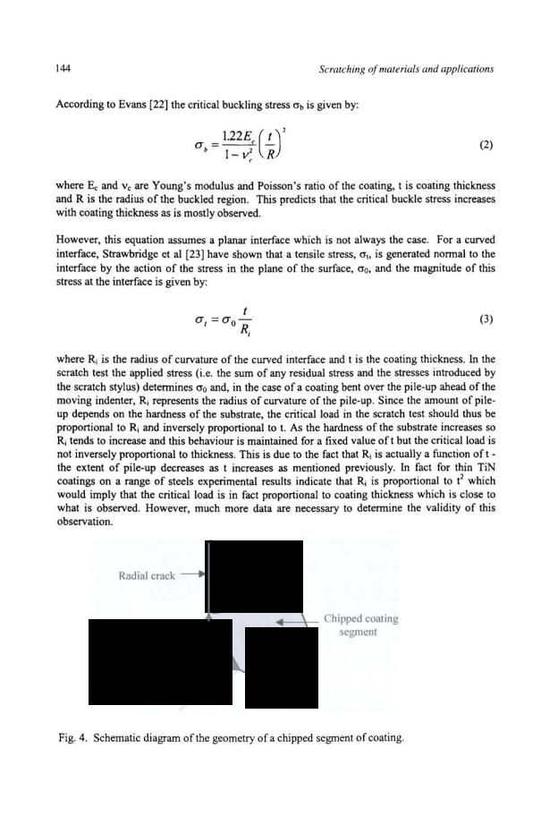
where E is the Young's modulus of the coating; t is the thickness of the coating; v is the Poisson's ratio of the coating; cr, is the residual stress in the coating and a, L and !3 define the geometry of the chipped piece (Figure 4). Reasonable values of interfacial toughness for hard films on silicon, glass and other hard substrates are produced by equation (4). This approach may be applied to cracks associated either with static indentations or scratches but the fracture energy is generally different in the two cases which implies that there is a frictional contribution to the failure in the scratch test which has not been considered.
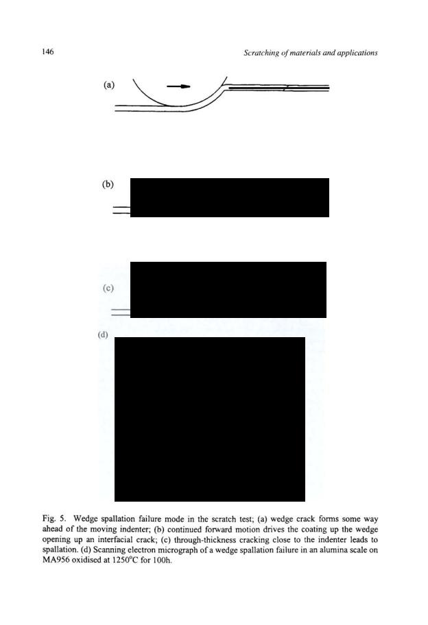
Wedge Spallation: For thicker (>lO!J.m) coatings where bending is less common the buckling failure mode is not observed. In fact the coating can suppress the formation of a narrowly defined pile-up region (Figure 5d) and the stresses ahead of the indenter are less complex. Adhesive failure now occurs by a different mechanism (Figure Sa-c). Initially compressive shear cracks form some distance ahead of the indenter through the thickness of the coating. These propagate to the surface and interface and generally have sloping sides which can act like a wedge. Continued forward motion of the indenter drives the coating up the wedge causing an interfacial crack to propagate. As the extent of interfacial failure increases the wedge lifts the coating further away from the substrate creating bending stresses within it. Large enough displacements will cause a region ahead of the indenter to be detached in response to the tensile bending stresses created. When this happens the scratch diamond tip can drop into the hole left by removal of the coating (Figure 5d) and there is a dramatic increase in scratch width and scratch depth. Pile-up is then often seen beside the track until the stylus climbs up the wedge and out of the hole. Whereas such large failures are often observed for alumina scales on MA956, much smaller failures are often produced for vapour deposited TiN coatings and it is rare that the stylus drops into the hole left by the spalled coating. In this case the stylus passes over the edge of the spalled region creating considerable microfracture in the coating as it passes.
The wedge spallation failure mode depends on two distinct processes occurring [22]. Firstly a compressive shear crack must form and then interfacial detachment occurs. According to Evans [22] the biaxial stress necessary to cause the wedge crack, crw, is given by