

книги / FISMA and the risk management framework the new practice of federal cyber security
..pdfMechanical analysis of the scratching of metals and polrmers at moderate and large strains |
27 |
contrary, the strain of the material is totally elastic (X very low), Hs112=2Hs=(E/( 1-u2 ))cote and J..Lo=O. So in the general case we can expect a relation of the form:
Jlo = Ft =2~(X)cotB
j |
w " |
(Jl== 0) |
(8) |
o~~(x)~l |
|
|
|
where l;(X) is an increasing function of the indentation index. We will discuss later the reliability of these relations and the influence of the (real) friction coefficient Jl.
ANALYSIS OF THE WEDGE SCRATCHING (2D CASE)
Before considering the three dimensional (3D) scratching, it is instructive to review briefly the two dimensional (2D) case where analytic and experimental results are available. Even in this apparently "simple" case there remain some open questions. This is not surprising because in all cases scratching involves free surface with unknown shape, and so the uniqueness of the theoretical solution of the equations is not insured.
Case ofa Rigid Plastic Material under Zero Friction
We consider first the rigid perfectly plastic (RPP) material (~:e=O; a 0==cry). This case can be analysed by the slip line field (SLF) method. Since the pioneering work of Challen and Oxley [21] it is now well established from an experimental and theoretical point of view that for low attack angle the wedge produces a ploughing flow and is supported by a frontal edge, the plastic wave, where the material is plastically sheared (Fig. 2a).
Material
a) The ploughing flow: the plastic wave [21]. |
b) The cutting flow (J.L=O). |
Fig. 2. Flow patterns in plane strain scratching; Interaction between a rigid wedge and a rigid perfectly plastic body.
If w and I (=DE) are respectively the width and the length of the contact, the force balance and the power balance are:
28 |
Scratching of materials and applications |
(9)
~u is the sliding velocity along the interface, e and Ep are respectively the thickness of the strained layer and the average plastic strain in this layer (Fig. 2a). So we can deduce from the current SLF model [21] an estimation of the mean plastic strain induced in 2D ploughing. Under zero friction where Jlo=tan~, the contact pressure p which is uniform and Ep are:
(10)
For high attack angle, it is sure that cutting occurs, but various complex SLF models have been proposed. We consider here the very approximate, but simple model of Merchant where the chip is formed by a single velocity discontinuity with the shear angle $ [22]. Under zero friction $ =~12 and the chip has the same thickness than the feed e (Fig. 2b). It provides a very simple expression for the plastic strain of the chip:
&c =~co{~) (p = 0) |
(11) |
We see in Fig. 3 that the ploughing strain Ep increases with the attack angle as expected, but this increase is much higher than tan~: for example for ~=20 deg for which tan~=0.36, This strain becomes infinite for J3=45 deg which is the highest attack angle for this SLF model. On the contrary the cutting strain Ep is a decreasing function of~ and becomes
lower than Ep for ~>30 deg. This very simple model suggests the existence of a critical attack angle ~c~30 deg. This conclusion is in rather good agreement with more elaborate models: kinematic models of ploughing flow [23] cannot be built for close to ~>15 deg and this suggests a change in flow pattern for higher attack angles. Petryk [24] has built various SLF models of wedge scratching and has demonstrated that the plastic wave flow dissipates higher power than
a composite flow inducing cutting and ploughing for (3>20 deg. This result |
suggests that the |
critical attack angle in the plane strain scratching ofRPP solids under zero friction is: |
|
Pc ~ 20 deg for 2Dscratching of RPP solids and Ji =0 |
(12) |
Mechanical analysis ofthe scratching of metals and polymers at moderate and large strains |
29 |
|||||||||||||||
|
10 |
|
|
|
|
|
|
|
|
|
|
|
|
|
|
|
|
|
|
& |
|
|
|
|
|
|
|
' |
& |
|
|
|
|
|
|
|
|
|
|
|
|
|
|
|
|
|
||||
|
|
|
|
|
|
|
|
|
|
|
|
|
|
|||
|
|
|
|
c |
|
|
|
|
|
|
|
p |
|
|
||
|
8 |
|
|
|
|
|
|
|
Friction |
:i=lasticity |
|
|
||||
|
|
|
|
|
|
|
|
|
|
|
||||||
|
|
|
|
|
|
|
|
|
/'Work· |
|
|
|||||
c. |
6 |
|
|
|
|
|
|
|
|
|
|
/hardening |
|
|
||
|
|
|
|
|
|
|
|
|
|
~sity |
|
|
||||
II)-.., |
|
|
|
|
|
|
|
|
/ |
|
|
|||||
II) |
|
|
|
|
|
|
|
|
|
|
|
|
|
|
|
|
|
|
|
4.3 |
|
|
|
|
|
|
|
|
|
|
|
|
|
|
4 |
|
|
|
|
|
|
|
/ |
|
|
|
|
|
|
|
|
|
|
|
|
|
|
|
|
|
|
|
|
|
|
|
|
|
2 |
|
|
--- -/ |
|
|
|
|
/ |
|
|
|
|
|
|
|
|
|
|
/ |
|
|
|
|
|
|
|
|
|
|
|
||
|
0 |
|
- |
|
Ploughing |
Cutting |
|
|
|
|
||||||
|
|
|
--- |
|
|
|
|
|
|
|
|
|
|
|
|
|
|
|
|
|
|
|
|
|
|
|
|
|
|
|
|
|
|
|
|
0 |
10 |
|
20 |
li c=30 |
|
40 |
|
|
|
|||||
p(deg)
Fig. 3. Plane strain scratching of a RPP body: Evolution of the cutting Ec and ploughing Ep strain and evaluation of the critical attack angle; Schematic evolution of Ec and Ep with friction and rheology of the body.
This conclusion is, to a first approximation, in agreement with various experimental results where a transition between pure ploughing and a cutting-ploughing flow is observed and for work-hardened metals this occurs at between 15 and 30 deg [25, 26].
Influence ofFriction, Elasticity and Work hardening
Figure 3 provides a very simple mean for discussing the influence on the critical attack angle of the various rheological characteristics of real materials: elasticity Ee, strain sensitivity aao I a&
and strain rate sensitivity aa0 I a£ . At first insight we do not expect that such characteristics
have a very significant influence on the cutting strain Ec(P ). On the contrary, an increase in these quantities produces a very significant increase in the strained depth e (Fig. 2a) and so decreases Ep(p). The effect of the workhardening exponent Olna0 I olnc has been demonstrated with a
kinematic model of ploughing [27]; numerical simulation will demonstrate the effect of elasticity below. So we can expect that the critical attack angle increases with elasticity, strain and strain rate sensitivity (Fig. 3). Recent numerical simulations [28] of 2D scratching of silicon (t:.-3.4 %) demonstrate that the critical attack angle is comprised between 22.5 and 30 deg, this higher value than 20 deg (relation (12)) could be due to elasticity. Experiments suggest that a prior workhardening of metals which reduces their strain sensitivity decreases Pc despite the fact that Ee is increased [25].
It is difficult to predict without any calculations the influence of friction because an increase in friction produces a very marked decrease in the thickness e of the strained layer (Fig. 2a) and in the shear angle cp (Fig. 2b) and finally a simultaneous increase in Ec(P) and Ep(p) (Fig. 3). This
30 |
Scratching of materials and applications |
question remains open. Experiments suggest that f3c increases with friction which would promote ploughing flow [26]. But from a theoretical point of view an increase in friction reduces the highest value of the attack angle for which the plastic wave SLF model (Fig. 2a) can be built [21, 24]. Recent numerical simulations [28] demonstrate that for an increase in friction the plastic wave and the chip degenerates into an adhesive edge (or built up edge) which is similar to the SLF "wear" model [21] where the frontal edge is a dead zone separated from the material by a velocity discontinuity line. Finally, notice that in ploughing flow the contact pressure decreases with an increase in the attack angle or in friction [21].
Application to the three dimensional scratching
All these conclusions are certainly qualitatively correct in three dimensional scratching but it is difficult to compare directly both the configurations. For example we are not able to define a shape ratio c (relation (5)) in 2D scratching. For the other quantities, to a first approximation, we can propose an equivalence through the apparent friction coefficient: for a conical indenter with a semiapical angle 8, the attack angle f32D of a wedge inducing the same apparent friction coefficient under zero friction is:
fJw =a tan(;cote) |
(13) |
In § 5-6 we consider the cone with 8=70.3 deg; it is the equivalent cone with equal volume for a given penetration depth to the Berkovich and Vickers pyramids in indentation. This cone would be equivalent to a wedge with the attack angle f32D-12.8 deg well below the critical attack angle and for which Ep-1.12 and p-2.45 cr0 . but for the same criterion the equivalent wedge attack angle of the Vickers (Berkovich) pyramid,would be (320-15.9 (13) deg for edge scratching and i32D-22 (24.7) deg for face scratching, all values higher than that related to the previous cone and for face scratching higher than f3c· For the Rockwell C indenter (8=60 deg) the equivalent wedge attack angle is (32D-20.2 deg, a value near f3c. for which Ep-2.05 and p-2.15 cr0• Finally the more acute indenter considered (8=20 deg) corresponds to f32D-60.2 deg. These results are of interest for the § 7.
CONDITIONS OF THE NUMERICAL SIMULATIONS OF SCRATCHING AND INDENTATION
Computer Code and Computation Conditions
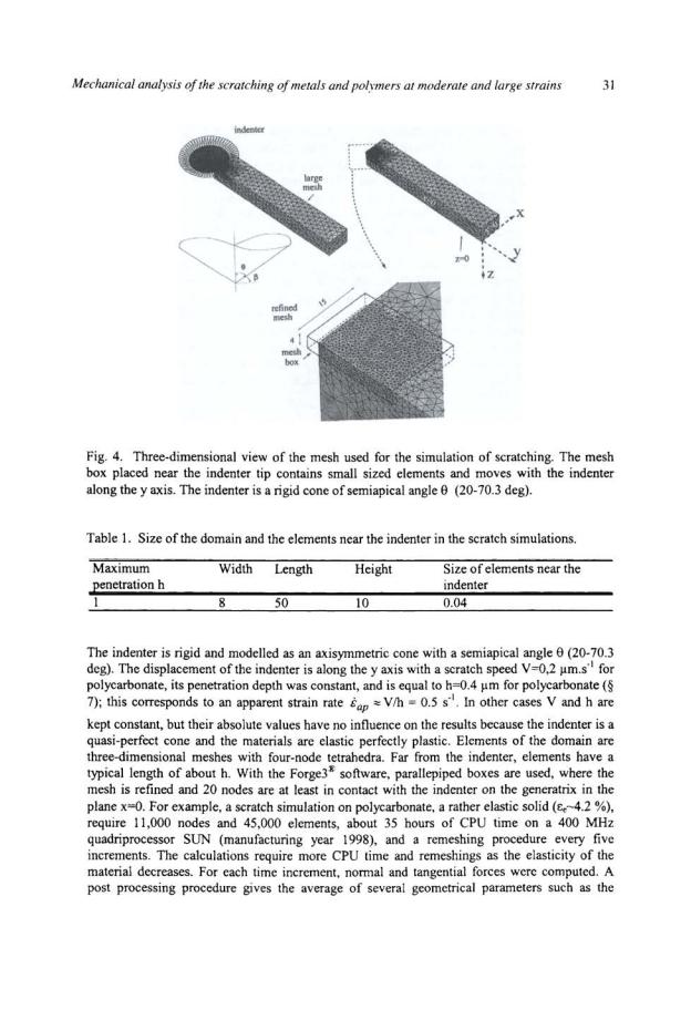
Scratching simulations are modelled using the Forge3® implicit code using an automatic remeshing procedure. The domain is a right-angled parallelepiped. Fig. 4 shows half of the finite-element mesh corresponding to the region x>O, with the plane x=O, a symmetry plane. The displacements of the mesh in the other directions were prevented by two planes y=O and z=O which are also considered as symmetry planes. The size of the domain was generally chosen (Table I) so that boundary effects do not influence the results.
32 |
Scratching of materials and applications |
scratch width, b, the frontal pile-up height, hbr , the residual depth, hr (Fig. 1) and so on. The indentation test(§ 5) is modelled with Forge2®, a two dimensional axisymmetric finite element code. A two-dimensional rectangular mesh incorporating six-node elements is constructed. Elements have a length of 0.04hmax near the indenter and of 3hmax far from the indenter. The rigid indenter is modelled as an axisymmetric cone with a semiapical angle 8=70.3 deg. The CPU times required for the calculations of indentation are very much smaller than those required for the simulation of scratch test.
More details concerning simulation of the scratch test and indentation test are given in [29,30). Examinations of the results of the simulations of scratching demonstrate that despite our cautions they involve some scatter and errors due to numerical error. In addition, the numerical simulations described in § 5-7 have been performed in different steps of the study and we observed some difference in results related to the same nominal condition (X=IOO, J.L=O). This is probably due to some difference in meshing-remeshing procedures which have not been always optimal. But it is reminded that at present time such a calculation of the scratch test remains a very difficult task and despite these limitations, we can draw some very clear conclusions about the main aspects of the studied problems.
Constitutive equations
All materials are considered homogeneous. The inertial forces are assumed negligible. We assume that at each time the strain rate tensor is the sum of an elastic strain rate tensor and a plastic strain rate tensor (elastoplastic material):
(14)
The elastic behaviour is modelled by a linear law with two constant parameters: Poisson's ratio, u, and Young's modulus, E; it means that the viscoelasticity of polymers is neglected. The yield condition is given by the von Mises yield criterion with the flow stress cro and the associated flow law. We define the generalised strain rate and the generalised strain by the classical relations:
.!. - |
~.pi. pi |
1/2 |
|
& - |
( 3 &!j &lj ) |
c = f&dr |
(15) |
For the polymer, the flow stress is described by a simplified G'sell-Jonas law [31 ]:
(16)
where cr1 is the strength coefficient, hg is the strain hardening coefficient and m the sensitivity to the strain rate. Isotropic hardening is assumed and so no Bauschinger effect (decrease in flow stress) occurs as the stress is reversed. The values of the rheological parameters used in the numerical simulations are summarised in table 2.

Mechanical analysis of the scratching of metals and polymers at moderate and large strains |
33 |
Table 2 Mechanical properties and values of the friction coefficient used in the numerical simulation of the scratch test
Material |
E (GPa) |
u |
cr1 (GPa) |
m |
hg |
jl |
Material(§ 5) |
E |
0.3 |
-0.35.10"3-0.35 E |
0 |
0 |
0 |
Steel(§ 6-7) |
210 |
0.3 |
0.75 (t:.-D.35 %) |
0 |
0 |
0-0.2 |
Polycarbonate (§ 7) |
2.4 |
0.35 |
0.102 (~:.-4.25 %) |
0.053 |
0.5 |
0.3 |
The values of the plastic parameters of the thermoplastic polymer polycarbonate considered in§ 7 have been deduced by an inverse method based on the interpretation by numerical simulations of the force-penetration curves of nano-indentation tests; in order to identify the various quantities these testings have been performed at various indenter speeds and with various indenter shapes [32]. They are in good agreement with the results of compression testings.
According to the value of the apparent strain rate |
1 |
|
tap z0.5 s· , the effective yield stress of |
||
polycarbonate is about: cry- |
102(0.5)0053 - 98 MPa -cr 1; so we will normalise for clarity the |
|
values of the hardness by |
cr 1. For 8=70.3 deg, |
its indentation index is X-8.4 whereas |
workhardened steel considered in§ 6 and 7 has an indentation index X-100. All thermal effects are neglected (cf. § 7).
Coulomb friction with coefficient Jl is imposed at the contact surface between material and indenter (Table 2). The value used for scratching the polycarbonate has been deduced from friction tests performed with a spherical tip [29]. Calculations with friction are very much time consuming especially for material with low elasticity (typically~:.- 0.35 %). In addition as it requires much more remeshings higher numerical errors are expected. For more elastic material, such as polycarbonate, calculations are easier and quicker.
ELASTIC EFFECTS IN LOW STRAIN SCRATCHING AND INDENTATION OF ELASTIC PERFECTLY PLASTIC SOLIDS
We study here the influence of the elasticity of the material characterised by E:e during the scratch test performed by a cone with the semiapical angle 8=70.3 deg under zero friction (Jl=O); the variation of E:e (table 2) induces a variation of the indentation index X between I and 103. The results are described in details in [33] and we shall here summarise the main conclusions. Notice that in [33] we name the shape ratio c2; we use here the notation cP =hclh proposed by Storakers and Larrson [34] for an indenter whose profile is described by a power law with an exponent p: a cone corresponds to p=1.

34 |
Scratching ofmaterials and applications |
|||||
Rear part |
• x Frontal part |
tx |
|
|
||
|
Rear part |
Frontal part |
||||
|
|
|
|
|
|
Increase |
|
|
|
|
|
|
|
|
|
|
....······· |
|
in X |
|
|
|
|
|
|
' |
|
|
|
|
|
|
\ |
|
|
|
0 |
|
|
·I-·-..· |
|
|
|
|
|
', y |
||
|
b./2= |
|
|
|
1 |
Lineof |
|
|
·...... |
|
equal |
||
|
ch tanS |
|
|
|||
|
|
|
|
|
contact |
|
|
|
|
|
|
r |
pressure |
a) X< 60: Decrease of the rear contact angle a and increase of the contact height.
b) X > 60: Contrctc:n the frontal part of the indenter and increase of the height (hrc is 10% greater than he).
Fig 5. Scratching elastic perfectly plastic solids with a 70.3 deg cone under zero friction: Schematic evolution of the contact surface (top view) with the indentation index X for a given penetration depth h.
Flow Pattern and Contact Geometry
As expected in § 3 the indenter induces in all materials a ploughing flow. Fig. 5 describes schematically for a given penetration depth h the evolution with the indentation index X of the contact geometry, one of the main unknown quantities of this problem.
This evolution comprises three main steps:
+For 1:s;X<10 about, the contact height is in first approximation uniform around the indenter and lower than the penetration depth h; so the shape ratio c is lower than I: the material sinks in before touching the indenter and remains in contact on the sides of the groove. In
first approximation the contact at the rear part is characterised by the angle a between the axis y=O and the line of detachment as it is observed on polymers [13) (Fig. Sa). As X increases, this rear contact angle a decreases whereas the shape ratio c increases (Fig. 6).
+ For 10 :s; X :s; 60, the evolution of the contact is very similar: the rear contact angle continues to decrease toward zero, but the material now piles up and the shape ratio c is greater than
I.
+ For 60<X :s; 1000, the contact is on the frontal part of the indenter; the material piles up in front of the indenter, then during the contact sinks under the indenter and turns around it; so the contact radius he is 10 % about smaller than the frontal contact radius hrc (Fig. 5b).
So a first quantity which characterises the contact geometry is the rear contact angle a. As we can observe on Fig. 6 its evolution with the indentation index X can be fitted by a polynomial regression:
I :s; X :s; 60 |
a= 78.229-1 03.14L + 60.93 IL2 -I 5.387L3 deg L =log X |
(1 7) |
{ Xz60 |
a=O |
|

Mechanical analysis of the scratching of metals and polymers at moderate and large strains |
35 |
|||||
|
|
|
|
|
|
|
80 |
|
a (deg) |
|
|
|
|
|
|
|
|
|
|
|
|
|
|
~ |
|
|
|
60 |
|
|
i |
|
||
|
|
1 |
|
|||
|
|
|
|
|||
|
|
L=log(X) |
j |
|
||
|
|
a= 78229-1 03.14•L |
1 |
|
||
40 |
|
+60.931•L 2-15.387•L 'j |
|
|||
|
|
I |
|
|
|
|
20 |
|
':( |
|
|
|
|
|
|
|
X |
|
|
|
|
|
|
|
|
|
|
0,1 |
10 |
100 |
|
|||
Fig 6. Scratching elastic perfectly plastic solids with a 70.3 deg cone under zero friction: Evolution of the rear contact angle a with the indentation index X.
A tentative extrapolation of the results suggests that a= 90 deg for X-0.8 (Fig. 6): it means that the contact would be limited by a full circle for X~0.8.
A first consequence of this evolution of the rear contact is that the apparent friction coefficient follows equation (8): Jlo increases with X and for X>60 it attains a limiting value very close the value 0.228 predicted by the classical equation (7) (Fig. 7). This result is in agreement with the experimental values related to lubricated scratching of metals by cones (for which X>60) [4]. The validity of the relation (7) for high value of the indentation index is explained by the fact that according to the numerical simulation in first approximation the contact pressure p decreases linearly with the radial distance r from the tip of the indenter toward the frontal limit (Fig. 5b). In [33] we demonstrated that the contact model of Fig. Sa provides a correct value of Jlo by the equation:
2 |
( cosa |
) |
) |
. |
(18) |
|
110 = -cotO |
( |
2altr |
|
am rad |
||
tr |
1+ |
|
|
|
|
|
So the equations ( 17) and (18) provide the evolution of Jlo with X.

36 |
|
|
|
|
Scratching of materials and applications |
|||
o~. |
0.228 |
~ 21fc codl |
|
, |
|
|
||
|
|
|||||||
|
|
|
|
|
|
|||
~0 |
---------------- -- -- ------ |
|
|
~ .~~ |
4 |
~ |
|
|
|
|
|
|
A |
|
|
|
|
0.15 |
|
|
|
|
|
|
|
|
0.1 |
|
|
|
|
|
|
|
|
|
|
|
|
|
|
X |
|
|
------ --------0·05':',--------f.;-,o |
,,±oo: |
|
d.,ooo |
|
|
|||
Fig 7. Scratching elastic perfectly plastic solids with a 70.3 deg cone under zero friction: Evolution of the apparent fiction coefficient ~0 with the indentation index X.
Before considering more in details the frontal geometry in scratching, it is instructive to remember the geometry of the indentations in the same materials calculated by RamondAngelelis (Fig. 8) [30]. Under load the material sinks in for X<30 (c<l) and piles up for X>30 (c>1). A very important result of these calculations is that elasticity has some influence in the whole range ofvalues ofthe indentation index because the indentation profile is not yet constant between X=200 and 1000. Even for X=lOOO, where the shape ratio c-1.25 we observe some slight elastic recovery during unloading. After unloading we observe in ail cases an indent with a bulge. If the indent is not very marked for the quasi-elastic case X=l and even X=S, the bulge is apparent for X~ 10 and the radial distance to the indentation axis of the residual bulge top a' is related to the contact radius a under load by a'/a=l+()(X) with ()(X) a decreasing function of X which tends toward 0; in addition ()(X) < 10 % for X~ 10: so the measurement of the residual indent radius a' provides an under-estimation of the true indentation pressure H= WI(m:/) with an error lower than 20 %.
|
|
|
|
after unloading |
|
under load |
|
|
|
|||
0.2 |
|
|
|
|
|
|
|
|
|
|
|
|
i-o.2 |
|
•·•·X=1 |
|
|
|
|
|
|
|
|
||
"0 |
|
|
|
|
|
|
|
|
|
|
||
c:: |
|
- |
X=S |
|
|
|
|
|
|
|
|
|
1.0.4 |
|
|
- |
X=10 |
|
|
|
|
|
|
|
|
|
|
- |
X=20 |
|
|
|
|
|
|
|
|
|
|
|
|
|
|
|
|
|
|
|
|
||
~ .0.6 |
|
|
-·X=30 |
|
|
|
|
|
|
|
|
|
|
|
- |
X=60 |
|
|
|
|
|
|
|
|
|
.s |
|
·-·X=80 |
|
|
|
|
|
|
|
|
||
.0.8 |
|
|
-X= 100 |
|
|
|
|
|
|
|
|
|
|
|
- |
X=200 |
|
|
|
|
|
|
|
|
|
|
|
|
--X= 1000 |
|
|
|
|
|
|
|
|
|
|
|
|
|
|
|
~ |
|
|
|
|
|
|
~5 |
|
~ 4 |
4 |
0 |
2 |
3 |
4 |
5 |
||||
indentation radius
Fig 8: Indentation of elastic perfectly plastic solids with a 70.3 deg cone under zero friction: Evolution with the indentation index X of the indent profile under load and after unloading [30].